
Method and device for controlling waste heat recovery system of kiln

A waste heat recovery system and control method technology, applied in the direction of furnace control devices, furnaces, waste heat treatment, etc., can solve the problems of high operation intensity and difficulty, inflexible operation, and low control accuracy, so as to reduce the operation intensity and difficulty, Improve control accuracy and prevent misoperation

Inactive Publication Date: 2009-12-09
霍镰泉 +1
View PDF0 Cites 6 Cited by
  • Summary
  • Abstract
  • Description
  • Claims
  • Application Information

AI Technical Summary

Problems solved by technology

At present, the kiln waste heat recovery system mostly adopts manual operation, and its operation is not flexible enough, the operation intensity and difficulty are high, the control accuracy is low, and it is easy to misuse

Method used


Image

  • Method and device for controlling waste heat recovery system of kiln
  • Method and device for controlling waste heat recovery system of kiln
  • Method and device for controlling waste heat recovery system of kiln

Examples


Embodiment Construction

[0044] The following will be described in conjunction with the accompanying drawings and embodiments.

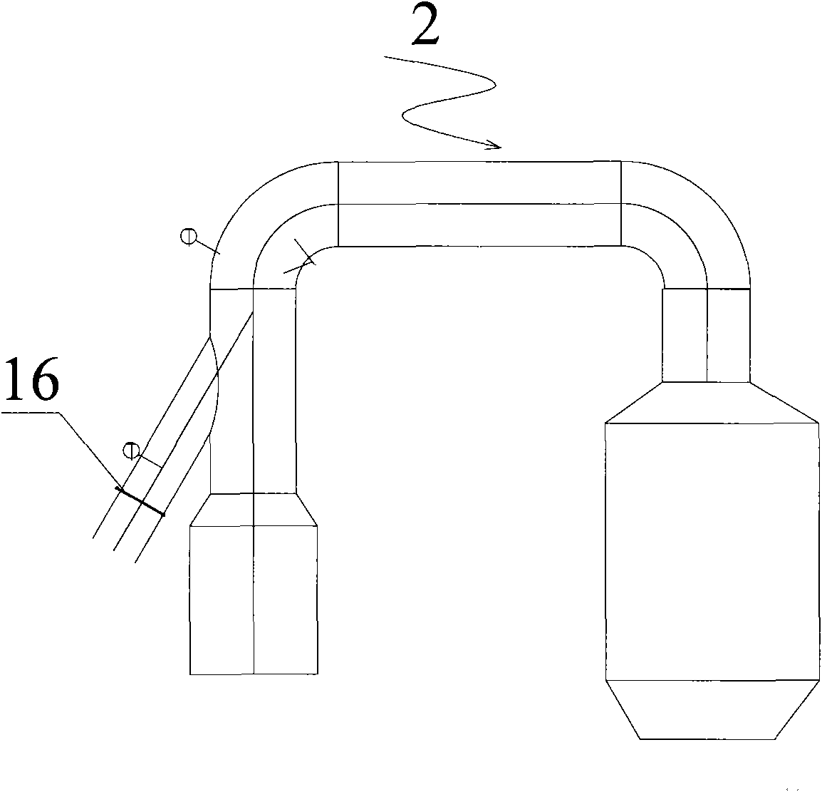
[0045] See figure 1 , figure 2 ,in: figure 1 It is a schematic diagram of the roller kiln in the kiln waste heat recovery system of the present invention; figure 2 It is a schematic diagram of the spray drying tower in the kiln waste heat recovery system of the present invention. The control method of the kiln waste heat recovery system of the present invention is specifically adapted to figure 1 , figure 2 The shown kiln waste heat recovery system includes a roller kiln 1 and a spray drying tower 2; the quenching section 3 of the roller kiln 1 is provided with a quenching fan 4 and a heat exchange box 6 with a heat exchanger 5 inside. Body 6 communicates with spray drying tower 2 through first pipeline 7, and is cut off from the quenching channel of roller kiln 1; end cooling section 8 of roller kiln 1 is provided with waste heat fan 9 and exhaust hood 10, and this ...


PUM


Abstract

The invention discloses a method for controlling a waste heat recovery system of a kiln. A quench section of a roller kiln of the system is provided with a quench fan and a heat exchange box body internally provided with a heat exchanger, is communicated with a spray drying tower through a first pipeline, and is partitioned from a quench channel; a tail cooling section is provided with a waste heat fan and an aspirator, and is communicated with the heat exchange box body through a second pipeline, and the second pipeline is provided with a discharge flue; and the waste heat recovery system also comprises a first control valve, a second control valve, a third control valve and a fourth control valve which are arranged on the discharge flue, the second pipeline, the first pipeline and a pipeline of a hot air furnace of the spray drying tower respectively. The method comprises the steps of: acquiring the temperature of tail cooling air of the tail cooling section of the roller kiln; and judging whether the temperature of the tail cooling air is higher than the preset kiln temperature, outputting a first control valve closing signal as well as second control valve, third control valve and fourth control valve opening signals if the temperature of the tail cooling air is higher than the preset kiln temperature; and outputting a first control valve opening signal as well as second control valve, third control valve and fourth control valve closing signals if the temperature of the tail cooling air is not higher than the preset kiln temperature. The invention also discloses a device for controlling the waste heat recovery system of the kiln. The method and the device can reduce operation strength and difficulty, improve control accuracy, and prevent the misoperation.

Description

technical field [0001] The invention relates to a device for utilizing waste heat, in particular to a control method and a control device for a kiln waste heat recovery system. Background technique [0002] Most ceramic production lines use roller kiln to burn products, and use spray drying tower to manufacture powder. Among them: when the roller kiln is firing products, the heat of the actual fired products is only about 1 / 3, and the rest of the heat is dissipated through the kiln and The smoke exhaust section at the kiln head and the cold section at the kiln tail are directly discharged outside, and its thermal efficiency is very low, resulting in a lot of energy waste; the spray drying tower is usually installed at the kiln head, mainly to use hot air to dry the mud into powder, which requires Lots of fuel to generate hot air. [0003] At present, the kiln waste heat recovery system has been widely accepted by building materials and ceramic factories. Since the system n...

Claims


Application Information

Patent Timeline
IPC IPC(8): F27D19/00F27D17/00F27D21/04F26B21/00
CPCY02P70/10Y02P80/15
Inventor 霍镰泉彭芳
Owner 霍镰泉
Learn More