
Preparation method of shallow trench isolation structure

A technology of isolation structure and shallow trench, applied in the field of preparation of shallow trench isolation structure, can solve the problems of electric field concentration, sharp silicon surface, slow surface oxidation, etc.

Active Publication Date: 2009-12-02
SHANGHAI HUAHONG GRACE SEMICON MFG CORP
View PDF0 Cites 1 Cited by
  • Summary
  • Abstract
  • Description
  • Claims
  • Application Information

AI Technical Summary

Problems solved by technology

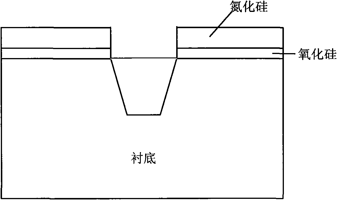
[0008] Using the above-mentioned traditional preparation method, since the upper surface of the shallow trench is covered by silicon nitride, and the side is exposed, when the pad is oxidized, the side is oxidized quickly, and the surface is oxidized slowly. The biggest difference in oxidation speed is at Figure 4 At the middle sharp corner, it is easy to cause the silicon surface to be sharper after oxidation, resulting in the thinning of gate oxide and the concentration of electric field.

Method used


Image

  • Preparation method of shallow trench isolation structure
  • Preparation method of shallow trench isolation structure
  • Preparation method of shallow trench isolation structure

Examples


Embodiment Construction

[0028] The preparation method of the shallow trench isolation structure of the present invention is integrated in the existing process, and mainly uses an etching process to etch to form a special silicon nitride morphology. The whole preparation process is as follows:

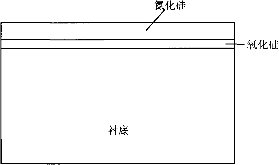
[0029] 1) Deposit silicon oxide and silicon nitride sequentially on a silicon substrate.

[0030] 2) Coating photoresist, performing shallow trench photolithography and developing, forming a photoresist opening. The specific settings in these two steps are similar to those in the prior art.

[0031] 3) Etching the silicon nitride by using the photoresist as a mask to remove part of the thickness of the silicon nitride, the thickness of the removed silicon nitride may be 20-60% of the total thickness of the silicon nitride layer;

[0032] 4) The lateral cutting of the photoresist, the opening of the photoresist in step 2 is enlarged by 10-50% (see Figure 7 ) This process can be carried out in the etching ch...


PUM


Abstract

The invention discloses a preparation method of a shallow trench isolation structure, which comprises the following steps: forming a scalar silicon nitride appearance used as a mask for etching a shallow trench through three etching technologies, and realizing that a top angle is smoothed to prepare smoother silicon and silicon oxide interfaces by utilizing thinner silicon oxide with a poorer oxidation shielding property when the inner surface of a shallow trench is subsequently oxidized.

Description

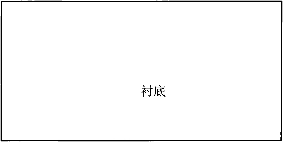
technical field [0001] The invention relates to a method for preparing a shallow trench isolation structure in semiconductor manufacturing. Background technique [0002] Shallow trench isolation (STI) is a relatively common isolation technology in semiconductor manufacturing, which mainly uses deposited silicon dioxide to backfill etched trenches to form isolation oxide regions. The preparation process of conventional shallow trench isolation structure (see Figure 1 to Figure 6 )for: [0003] 1) Deposit silicon oxide and silicon nitride sequentially on the silicon substrate; [0004] 2) Perform photolithography and development of shallow trenches, post-etch to form shallow trenches, and perform cleaning after etching (see image 3 ); [0005] 3) Oxidation treatment of the inner surface of the shallow trench forms a pad oxide layer (see Figure 4 ); [0006] 4) High-density plasma silicon oxide fills shallow trenches (see Figure 5 ); [0007] 5) planarization to form...

Claims


Application Information

Patent Timeline
IPC IPC(8): H01L21/762G03F7/42
Inventor 陈华伦陈雄斌熊涛陈瑜罗啸
Owner SHANGHAI HUAHONG GRACE SEMICON MFG CORP
Learn More