


Quick Research
Generate reliable direction feasibility study reports for your R&D in just a few steps.

Technical Q&A
Discover and master advanced knowledge NOW. Basics, ideas, possibilities, all at once.

Find Solutions
As an expert in R&D theories, this can generate solutions to your technical problems instantly.

Evaluate Feasibility
Analyze your overall solution with one click, know your potential R&D risks in advance.

Monitor Landscape
Get weekly tech updates, stay abreast of the latest tech innovations and key insights.
Rigid tension device with sensor
A sensor and tensioner technology, applied in instruments, vehicles for freight, parts of bundling machinery, etc., can solve the problems of the impact of bundled goods transportation, increase the difficulty, time-consuming and laborious, etc., to improve convenience and safety. performance, improve safety and reliability, and the effect of a simple overall structure
- Summary
- Abstract
- Description
- Claims
- Application Information
AI Technical Summary
Problems solved by technology
Method used
Image


Examples
Embodiment 1
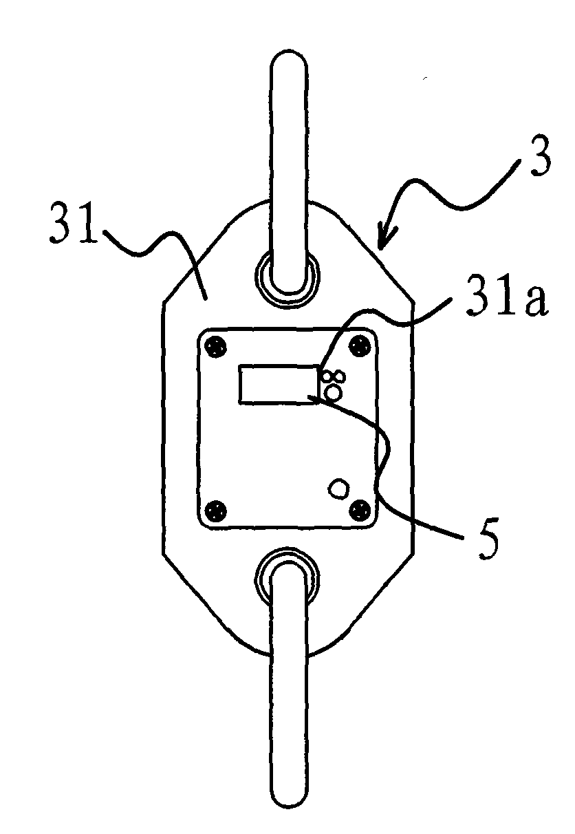
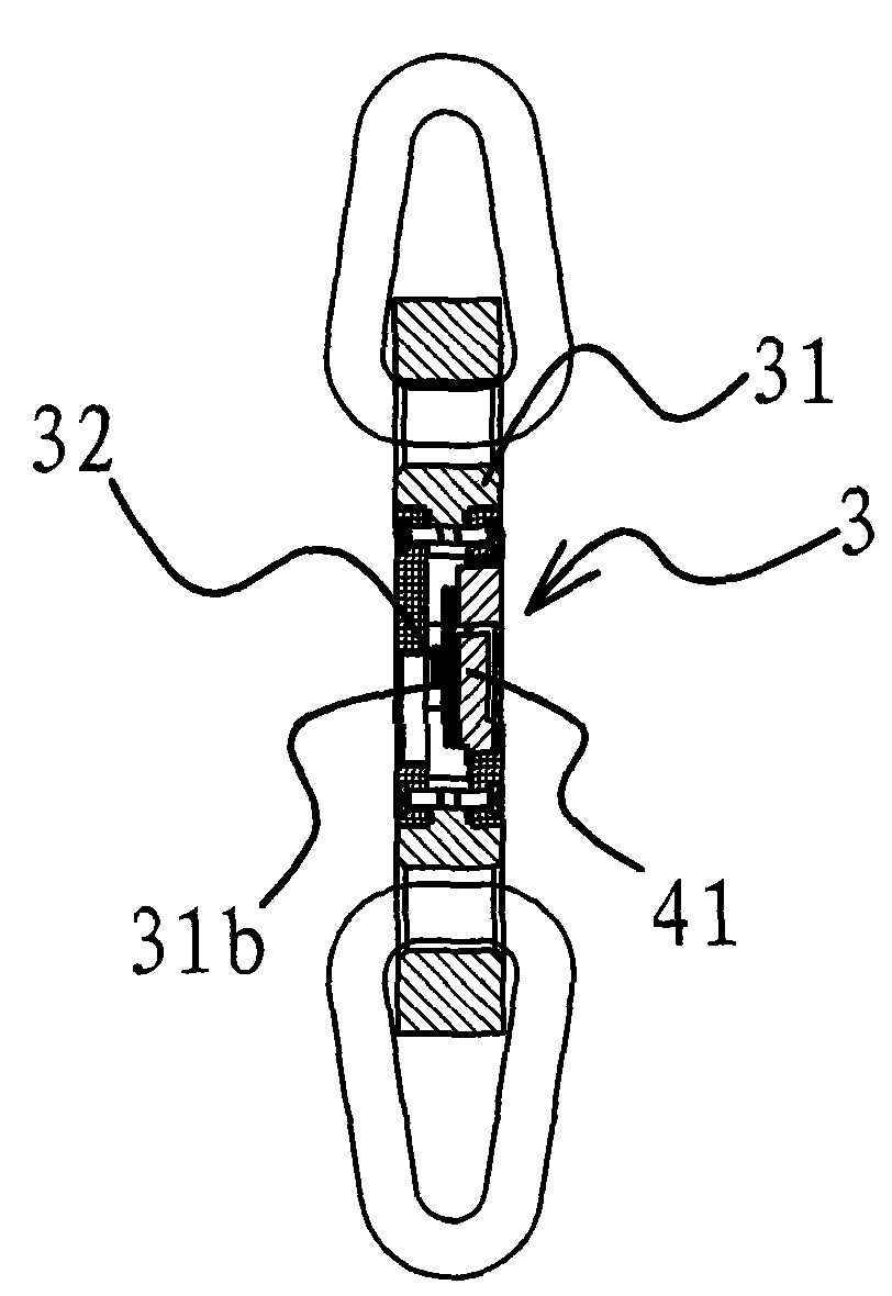
[0036] Such as Figure 1-6 As shown, the sensor-equipped rigid tensioner includes a tensioning mechanism 1 with a handle 11 , one end of the tensioning mechanism 1 is connected with the first hook 21 , and the other end is connected with the second hook 22 . The tensioning mechanism 1 here is made of rigid material, and the tensioning mechanism 1 can adjust the distance between the first hook 21 and the second hook 22 when the handle 11 is pulled. A sensor 3 is provided between the tensioning mechanism 1 and the first hook 21, and when the tensioner is in a working state, the sensor 3 can generate a signal corresponding to the magnitude of the tensioning force. The sensor 3 is connected with a signal processing circuit 4 capable of receiving and processing the above-mentioned signals, and the signal processing circuit 4 is connected with a display device for displaying the tension force.
[0037] Such as Figure 5 and 6 As shown, in this embodiment, the tensioning mechanism 1...
Embodiment 2
[0043] Such as Figure 7 As shown, in this embodiment, on the basis of Embodiment 1, a wireless signal transmitting module 51 connected to the signal processing circuit 4 capable of transmitting wireless signals and an external receiving device 52 capable of receiving the above-mentioned wireless signals are added. The signal of the tension force can be transmitted to the external receiving device 52 through the wireless signal transmitting module 51, and the external receiving device 52 can monitor the working state of the tensioner in real time. Since the external receiving device 52 is provided, simultaneous monitoring of multiple tensioners can be realized.
[0044] The rest of the structure in this embodiment is similar to that of Embodiment 1, and the working process of the sensor 3 and other components is also similar to that of Embodiment 1, which will not be repeated here.
Embodiment 3
[0046] In this example, if Figure 8 and 9 As shown, the tensioning mechanism 1 includes a connecting rod one 17 and a connecting rod two 18 . The outer end of the connecting rod one 17 is connected with one end of the sensor 3 , the other end of the sensor 3 is connected with a first hook 21 , and the outer end of the connecting rod two 18 is provided with a second hook 22 . The middle part of the handle 11 is hinged with the inner end of the second connecting rod 18, and the inner end of the handle 11 is hinged with the inner end of the first connecting rod 17. The hinge of 18 can swing to the bottom of connecting rod one 17 by connecting rod one 17 tops and be positioned. The middle part of the handle 11 has an outwardly protruding hinge portion 11b, and one end of the above-mentioned connecting rod 2 18 is hinged to the hinge portion 11b.
[0047] Pull the outer end of the handle 11 to make the handle 11 swing around its hinge with the connecting rod one 17 . During th...
PUM
 Abstract
Description
Claims
Application Information
 - R&D Engineer
- R&D Manager
- IP Professional
- Industry Leading Data Capabilities
- Powerful AI technology
- Patent DNA Extraction
Browse by: Latest US Patents, China's latest patents, Technical Efficacy Thesaurus, Application Domain, Technology Topic, Popular Technical Reports.
© 2024 PatSnap. All rights reserved.Legal|Privacy policy|Modern Slavery Act Transparency Statement|Sitemap|About US| Contact US: help@patsnap.com