Automatic material throwing belt

An automatic feeding and conveyor belt technology, applied in the direction of conveyor control devices, conveyor objects, conveyors, etc., can solve problems such as difficult tension effects, complex feeding belt structure, etc., and achieve the effect of improving efficiency and convenient production

Inactive Publication Date: 2018-12-07
WUHU NEW UNIVERSAL ENVIRONMENTAL SCI TECH
View PDF11 Cites 0 Cited by
  • Summary
  • Abstract
  • Description
  • Claims
  • Application Information

AI Technical Summary

Problems solved by technology

[0003] The purpose of the present invention is to provide an automatic feeding belt to solve the complex structure of the feeding belt in the prior art and the difficulty in controlling the tension effect during the working process

Method used


Image

  • Automatic material throwing belt
  • Automatic material throwing belt
  • Automatic material throwing belt

Examples


Embodiment Construction

[0018] In order to make the technical means, creative features, goals and effects achieved by the present invention easy to understand, the present invention will be further described below in conjunction with specific embodiments.

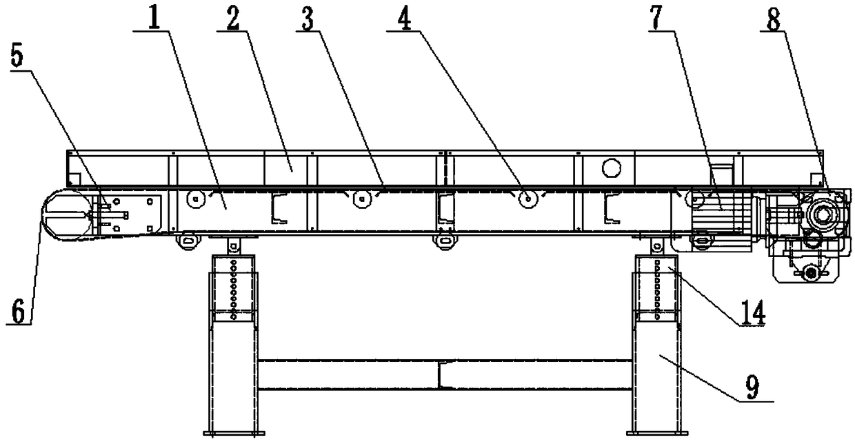
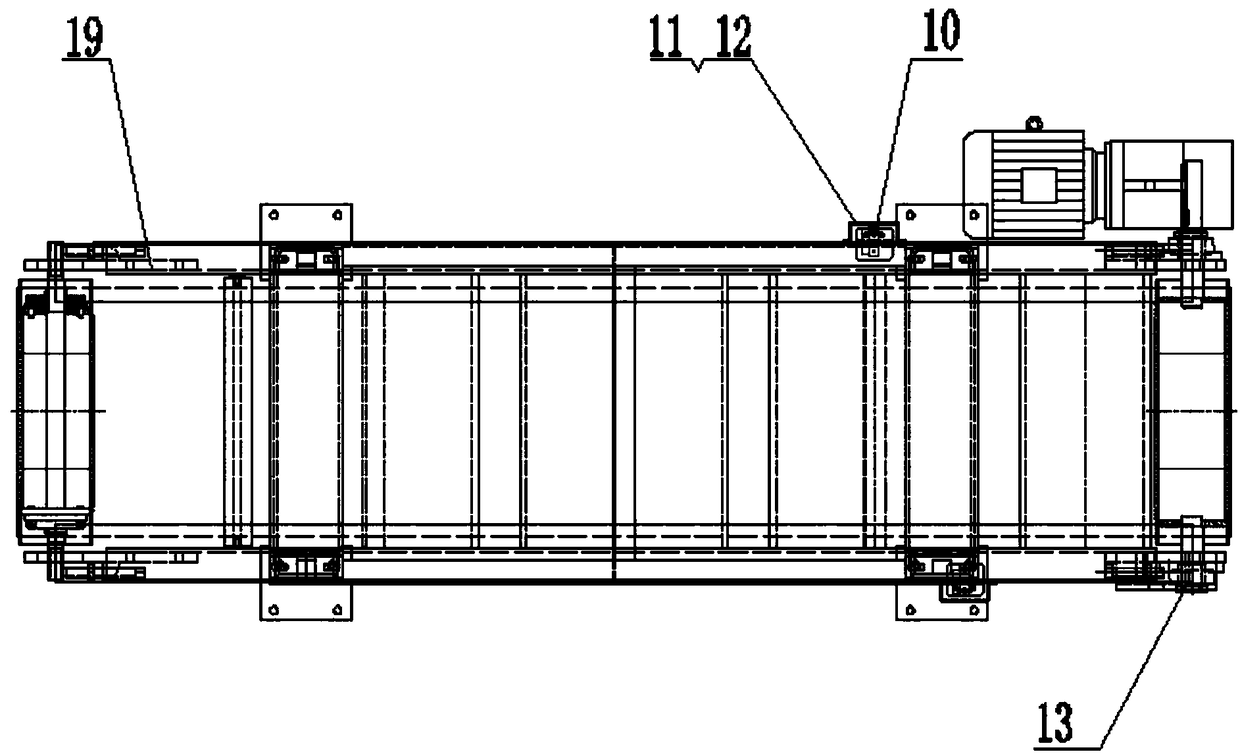
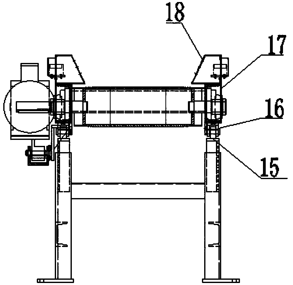
[0019] Such as Figure 1 to Figure 6 As shown, a kind of automatic feeding belt comprises frame 1, elevating bar 14, support leg 9, tail roller mounting plate 19, tail roller 6, tail roller shaft 55, conveyer belt 3 and tail roller tensioning device, the machine The frame is connected with the lifting rod, the lifting rod 14 is installed on the leg 9, the tail roller mounting plate 19 is installed at one end of the frame 1, and the tail roller tensioning device includes a tensioning motor 57 , gear 51, rack 52, spring 53, push block 54, rotating shaft 58, described tensioning motor 57 is fixed on the tail roller mounting plate 19, and the output end of described tensioning motor 57 is connected with rotating shaft 58, so Both ends of the rotating...


PUM


Abstract

The invention discloses an automatic material throwing belt. A machine frame is connected with lifting rods, and the lifting rods are installed on supporting legs; a tail roller installing plate is installed at one end of the machine frame, and a tensioning motor is fixed to the tail roller installing plate; the output end of the tensioning motor is connected with a rotating shaft, and the two ends of the rotating shaft penetrate through the tail roller installing plate and are sleeved with gears; the gears are engaged with racks, and the tail roller installing plate is provided with a guidinggroove in the same direction with a conveying belt; the racks are inserted and connected to the guiding groove in a sliding manner; one end of each spring is arranged on the end portion of the corresponding rack in a sleeving manner, and the other end of each spring is fixedly sleeved with a pushing block; the pushing blocks are fixedly connected with tail roller shafts, and pressure sensors arearranged on the outer surfaces of tail rollers; and the pressure sensors are electrically connected to a control element of the tensioning motor. The automatic material throwing belt is simple in structure, in the material conveying process of the material throwing belt, a tension device can stably adjust the tensile force of the conveying belt, using and transporting are stable, convenience is provided during production, and therefore the production efficiency is improved.

Description

technical field [0001] The invention relates to the field of conveying machinery, in particular to an automatic feeding belt. Background technique: [0002] We know that the feeding belt is a composite product of rubber, fiber and metal used to carry or transport materials during object conveying. The feeding belt is widely used in various industries such as steel, chemical industry, cement, etc., and the tensioning device and deviation correction device of the feeding belt are important components of the conveying device. The tensioning device mainly provides the necessary tension for the feeding belt, and the deviation correction device It is to prevent the wear of the feeding belt or the deviation of the transported materials; the current existing technology is to manually adjust the tail roller to realize the tension and deviation correction of the feeding belt, or the design of the tensioning device and deviation correction device in the prior art is relatively complica...

Claims


Application Information

Patent Timeline
Patent Type & Authority Applications(China)
IPC IPC(8): B65G23/44B65G15/64B65G43/02
Inventor 张跃东袁野
Owner WUHU NEW UNIVERSAL ENVIRONMENTAL SCI TECH
Why Eureka
Try Eureka