
Process and device for the production of channel-section glass elements, channel-section glass element and its use

A groove-shaped section, glass technology, applied in glass manufacturing equipment, glass molding, glass rolling, etc., can solve problems such as reduced possibility

Active Publication Date: 2009-11-25
BAUGLASINDUSTRIE GMBH
View PDF6 Cites 1 Cited by
  • Summary
  • Abstract
  • Description
  • Claims
  • Application Information

AI Technical Summary

Problems solved by technology

[0010] The problem underlying the invention is to make available channel-section glass elements which can be arranged side by side with a reduced possibility of visually sealed seams being seen.

Method used


Image

  • Process and device for the production of channel-section glass elements, channel-section glass element and its use
  • Process and device for the production of channel-section glass elements, channel-section glass element and its use
  • Process and device for the production of channel-section glass elements, channel-section glass element and its use

Examples


Embodiment Construction

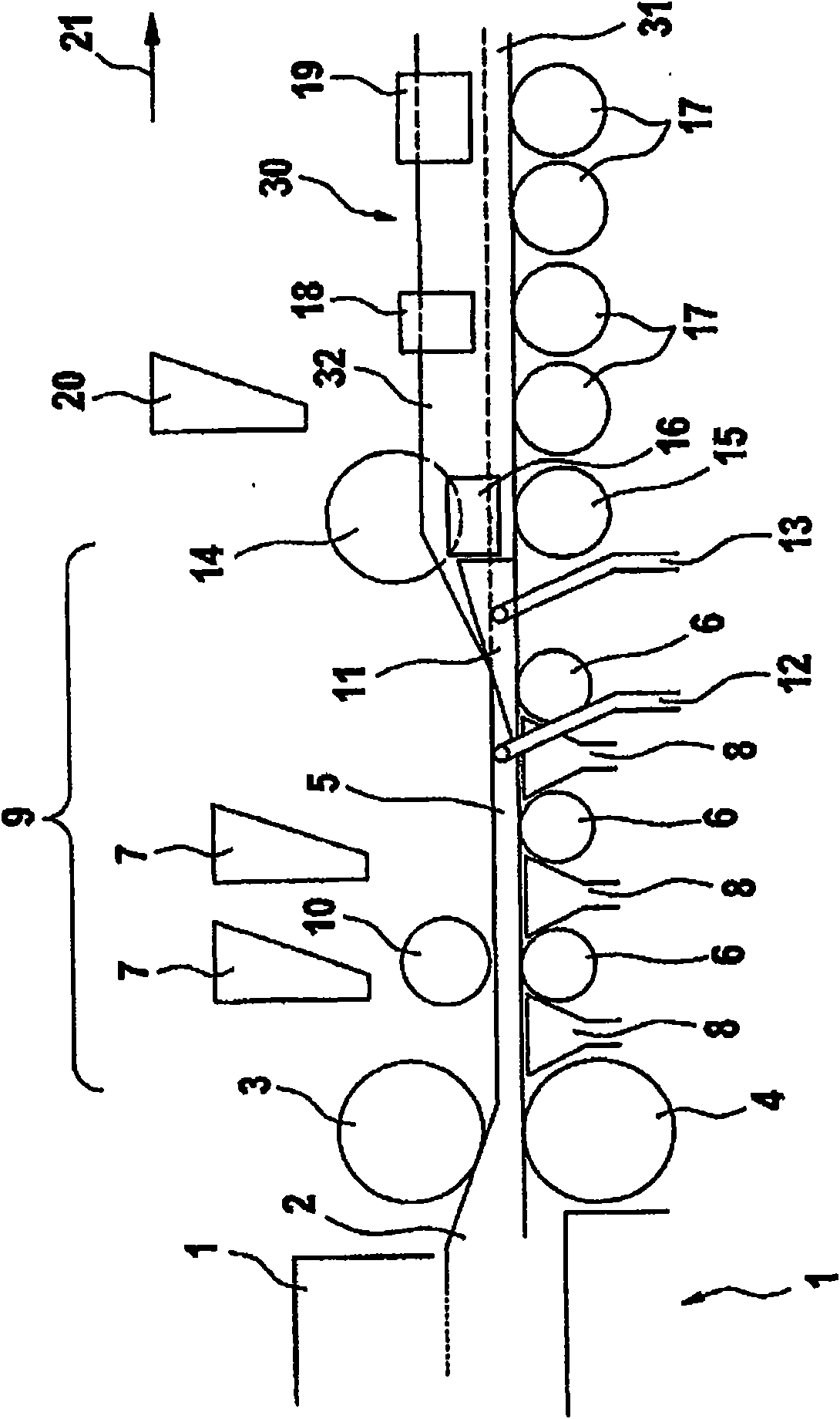
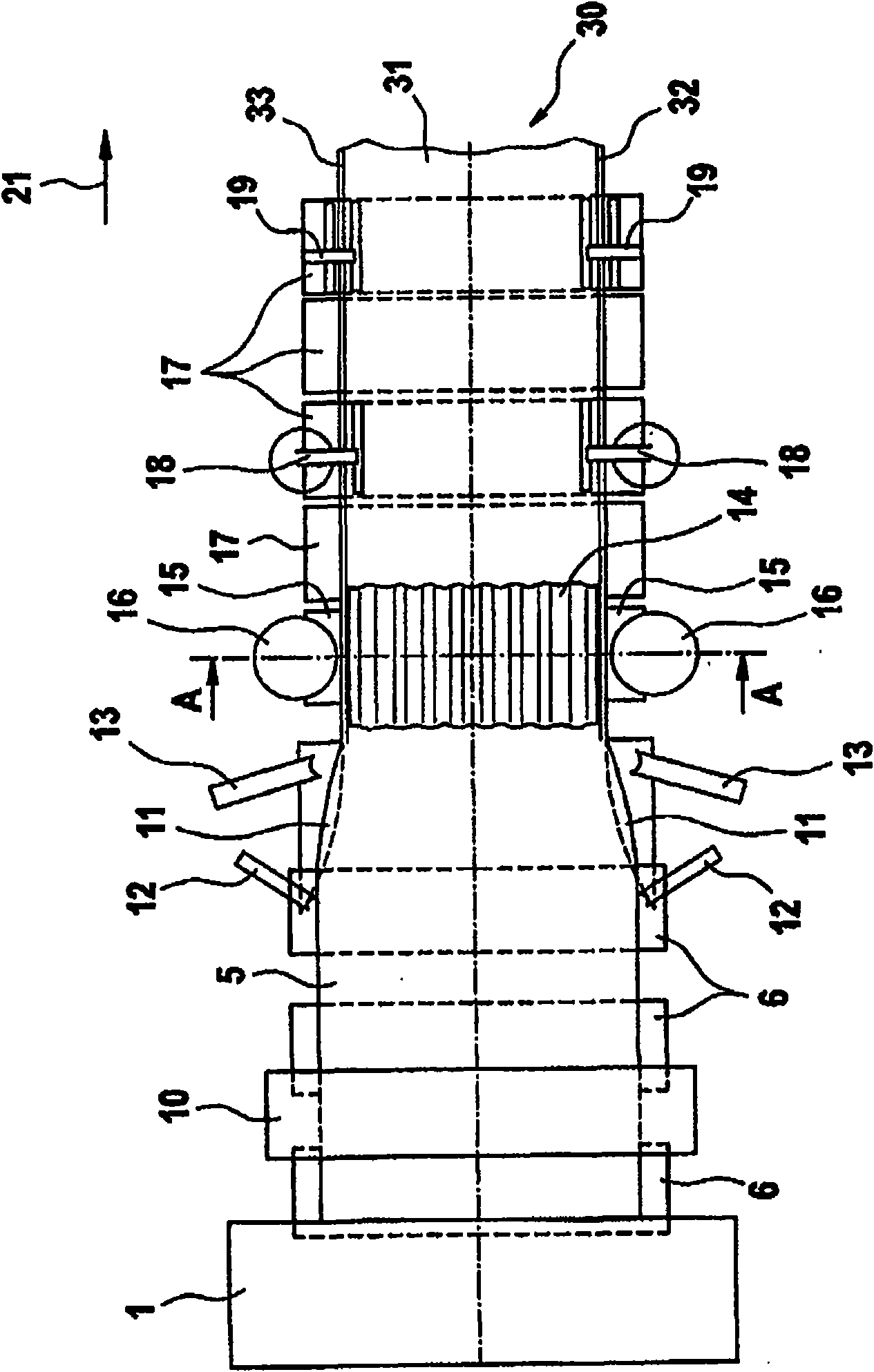
[0075] figure 1 A side view showing an embodiment of the inventive apparatus for the production of channel-section glass elements, while figure 2 A plan view of the device is shown.

[0076] The two cylindrical introduction rolls 3, 4, in which the two cylindrical introduction rolls 3, 4 are arranged to produce glass, have the same diameter and are arranged one above the other, leaving a nip of approximately constant width Standard design of melt 2 at the exit of glass melting furnace 1, which is in figure 1 , 2 shown only in general terms. A generally flat but still flexible glass ribbon 5 of predetermined thickness can be made (introduced from the melt) by means of the introduction rolls 3 , 4 . The lower introduction roll 4 has an irregular surface structure (pattern) transferred to the lower surface of the glass ribbon 5 .

[0077] The glass melt 2 of standard soda lime silicate glass has a temperature of the order of about 1100° C. in front of the introduction rolls...


PUM


Abstract

Process for the production of a channel-section glass element (30) with two flanges (32, 33) and a web formed between the flanges (32, 33), which comprises the following steps: a) making available a flat glass ribbon (5) by means of two cylindrial draw-in rollers (3, 4) disposed at the exit of a glass melting furnace (1) b) adjusting the temperature of the web (31) to a web temperature at which the web (31) is still plastically deformable, c) adjusting the temperature of the flanges (32,33) to a flange temperature which is lower then the web temperature, d) erecting the flanges (32,33) at the edges of the glass ribbon (5) e) profiling the web (31) with the aid of two web profiling rollers (14,15), in such a way that the web (31) has a corrugated cross-section, f) cooling the channel-section glass element (30). A device for the production of a channel-section glass element (30) is also disclosed, furthermore a channel-section glass element (30) producible by such process and device and its use.

Description

technical field [0001] The present invention relates to a method and an apparatus for producing a channel-section glass element having two flanges and a web formed between the flanges, a channel-section glass element producible by such a method and apparatus, and such a channel use of shaped cross-section glass elements. Background technique [0002] Channel-section glass elements have long been used as light transmissive (ie, transparent or translucent) structural elements. An elongated standard channel-section glass element has a U-shaped cross-section and has a central web forming the base of the channel and having a width of typically about 20-50 cm and a flange height typically of about 4-10 cm, the flange being approximately Continue at approximately right angles at the longitudinal edges of the web. The glass thickness usually amounts to about 5-10 mm. Channel-section glass elements are mainly used to close light openings in building facades (outer walls), but also...

Claims


Application Information

Patent Timeline
IPC IPC(8): C03B13/01C03B13/06C03B13/08E04C2/54
CPCC03B13/01C03B13/08E04C2/54C03B13/06Y02P40/57
Inventor N·沙伊德H·舍贝恩T·布劳恩C·克莱斯格斯
Owner BAUGLASINDUSTRIE GMBH
Learn More