


Quick Research
Generate reliable direction feasibility study reports for your R&D in just a few steps.

Technical Q&A
Discover and master advanced knowledge NOW. Basics, ideas, possibilities, all at once.

Find Solutions
As an expert in R&D theories, this can generate solutions to your technical problems instantly.

Evaluate Feasibility
Analyze your overall solution with one click, know your potential R&D risks in advance.

Monitor Landscape
Get weekly tech updates, stay abreast of the latest tech innovations and key insights.
Thick oil paraffin removal device for screw pump electric heating oil pipe
A technology of screw pumps and oil pipes, which is applied in the direction of pump devices, components of pumping devices for elastic fluids, pumps, etc., and can solve problems such as limited promotion and inability to solve insulation problems
- Summary
- Abstract
- Description
- Claims
- Application Information
AI Technical Summary
Problems solved by technology
Method used
Image

Examples
Embodiment 1
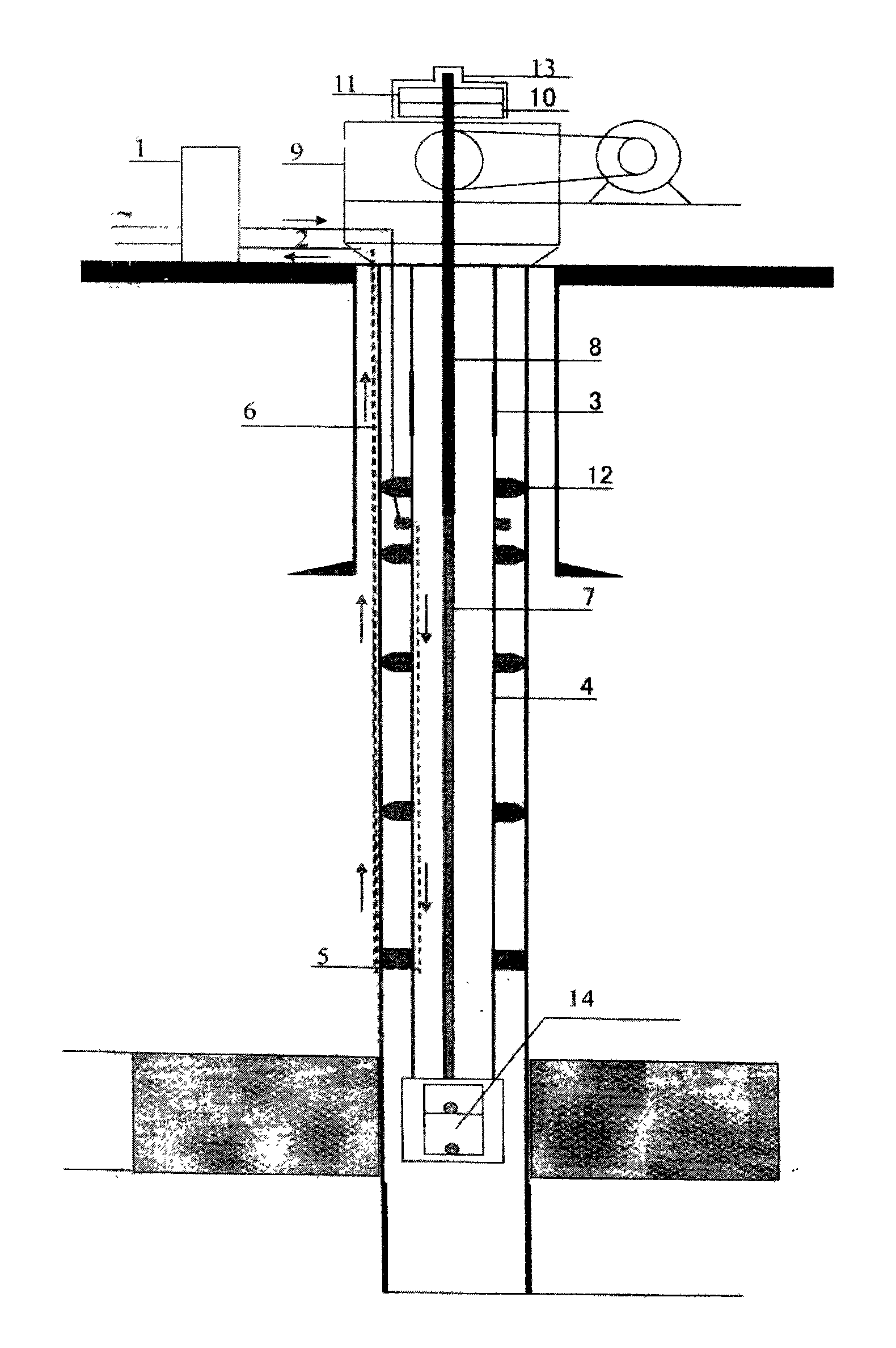
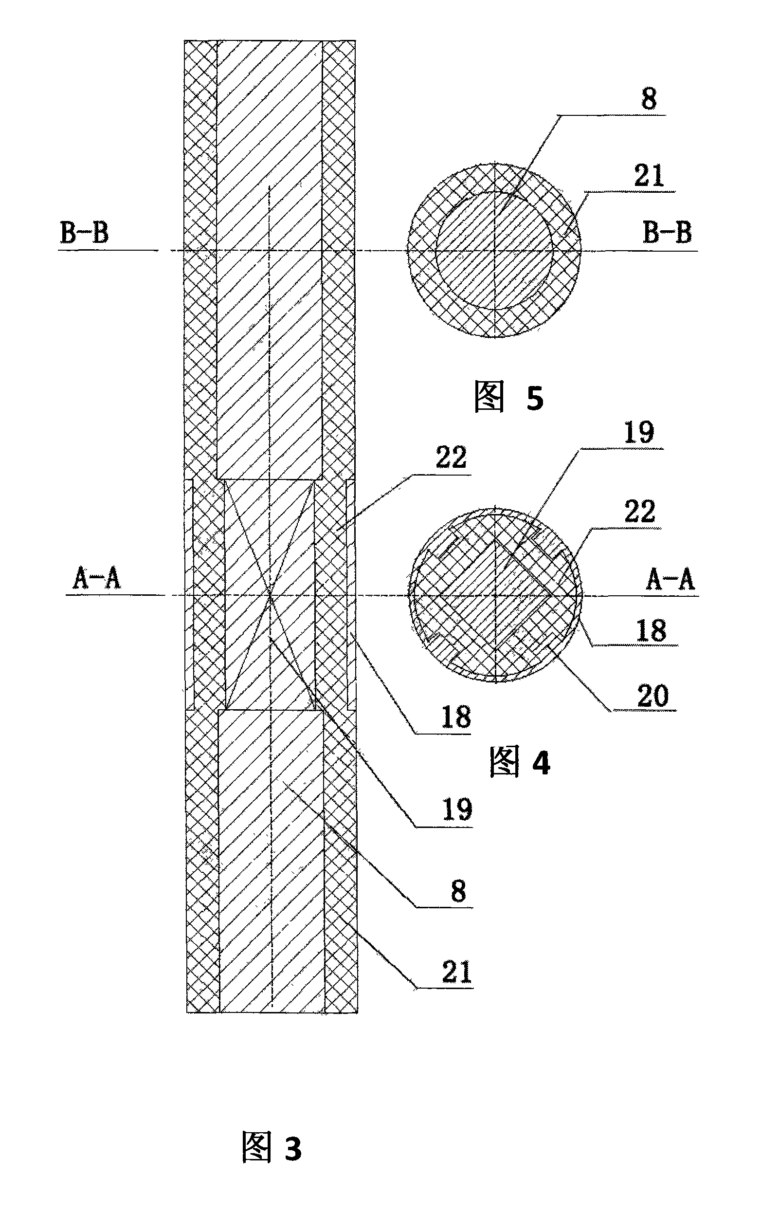
[0020] The structure of the present invention is as shown in the accompanying drawings: an electric control cabinet 1 is arranged on the ground. The oil pipe 4 is provided with an insulating nipple 3 . The electric control cabinet is connected to the oil pipe at the lower part of the insulating pup through the cable 2. There is a connector 5 between the lower part of the oil pipe and the casing 6 . The bushing passes through the connector as a current loop. An insulating centralizer 12 is provided between the oil pipe and the casing pipe. At the bottom of the oil pipe is a screw pump 14 . Rotating rod 7 is arranged on the screw pump, and an insulating polished rod 8 is arranged at the top of the rotating rod. An insulating sleeve 21 is provided on the outside of the polished rod. The insulating sleeve is made of nylon or fiberglass. There is a plane 19 around the middle section of the polished rod. This section of the polished rod with the plane is a tetrahedron. An in...
Embodiment 2
[0022] The structure of the present invention is as shown in the accompanying drawings: an electric control cabinet 1 is arranged on the ground. The oil pipe 4 is provided with an insulating nipple 3 . The electric control cabinet is connected to the oil pipe at the lower part of the insulating pup through the cable 2. There is a connector 5 between the lower part of the oil pipe and the casing 6 . The bushing passes through the connector as a current loop. An insulating centralizer 12 is provided between the oil pipe and the casing pipe. At the bottom of the oil pipe is a screw pump 14 . Rotating rod 7 is arranged on the screw pump, and an insulating polished rod 8 is arranged at the top of the rotating rod. An insulating sleeve 21 is provided on the outside of the polished rod. The insulating sleeve is made of nylon or fiberglass. There is a plane 19 around the middle section of the polished rod. The smooth rod with plane in this section is a hexahedron. An insulatin...
PUM
 Abstract
Description
Claims
Application Information
 - R&D Engineer
- R&D Manager
- IP Professional
- Industry Leading Data Capabilities
- Powerful AI technology
- Patent DNA Extraction
Browse by: Latest US Patents, China's latest patents, Technical Efficacy Thesaurus, Application Domain, Technology Topic, Popular Technical Reports.
© 2024 PatSnap. All rights reserved.Legal|Privacy policy|Modern Slavery Act Transparency Statement|Sitemap|About US| Contact US: help@patsnap.com