
Substrate transmission mechanism

A transmission mechanism and substrate technology, applied in the direction of conveyors, conveyor objects, transportation and packaging, etc., can solve the problems of shortened service life, high equipment cost, dust ingress, etc., and achieve increased service life, high cleanliness, and transmission smooth effect

Inactive Publication Date: 2009-11-18
DONGGUAN ANWELL DIGITAL MASCH CO LTD
View PDF0 Cites 39 Cited by
  • Summary
  • Abstract
  • Description
  • Claims
  • Application Information

AI Technical Summary

Problems solved by technology

Due to the direct contact between the substrate and the conveying roller in the above-mentioned transmission method, it is easy to cause mechanical wear of the substrate during the transmission process, which affects the accuracy and quality of the finished product; at the same time, due to the contact of various moving components such as gears and screw rods, the transmission is easy The moving components of the equipment are granulated due to friction, and the dust generated enters the substrate transfer area, which affects the cleanliness of the substrate and generates a lot of noise during the transfer process; in addition, the friction between the moving parts of the transfer The service life of each moving component is shortened, and the service life of the transmission equipment is also shortened accordingly
Another transmission method is to use industrial robots for transmission. Due to the high cost of equipment and the large footprint, its manufacturing cost is high, which limits large-scale production and application

Method used


Image

  • Substrate transmission mechanism
  • Substrate transmission mechanism
  • Substrate transmission mechanism

Examples


Embodiment Construction

[0021] Embodiments of the present invention will now be described with reference to the drawings, in which like reference numerals represent like elements.

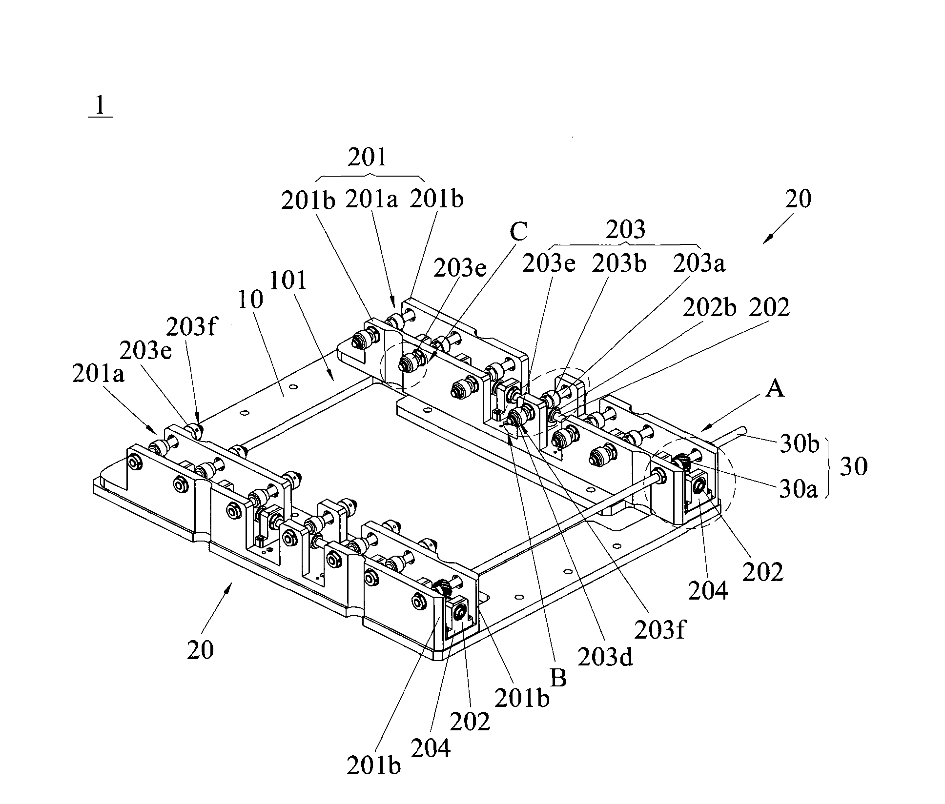
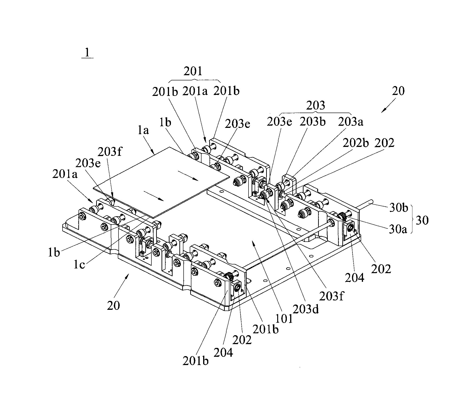
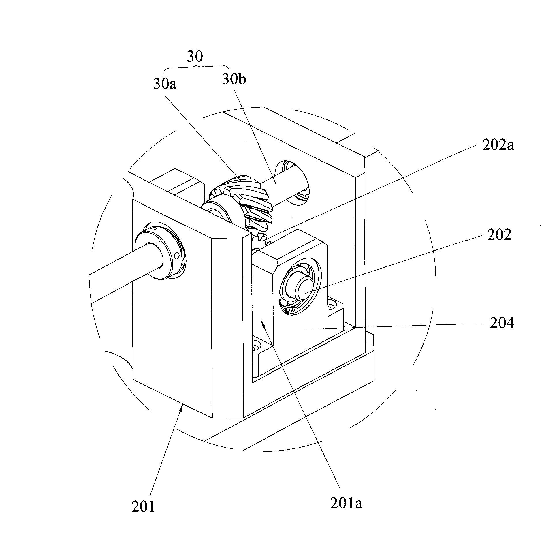
[0022] Such as Figure 1a , Figure 1b and figure 2As shown, the substrate transport mechanism 1 of the present invention includes a driving device (not shown), a main transmission device 30, a base plate 10 and two secondary transmission devices 20, the driving device is connected with the main transmission device 30, and the two secondary transmission devices 20 It is connected to both sides of the bottom plate 10 in parallel and is connected to the main transmission device 30 respectively. A transmission area 101 is formed between the two transmission devices 20. The driving device drives the main transmission device 30, and the main transmission device 30 synchronously drives the two transmission devices. The secondary transmission device 20, wherein, the secondary transmission device 20 includes a bearing housing 2...


PUM


Abstract

The invention discloses a substrate transmission mechanism, which comprises an actuating device, a primary transmission gear, a soleplate and two secondary transmission gears, wherein each secondary transmission gear comprises a bearing box, a magnetic transmission shaft, a first helical gear, and a plurality of first permanent magnetic gears and magnetic transmission units which correspond mutually; the bearing box is connected with the soleplate, the magnetic transmission units are parallelly pivoted with the bearing box, and are provided with roller wheels; the first helical gear is fixed on the magnetic transmission shaft, the primary transmission gear is provided with a second helical gear engaged with the first helical gear, and the first helical gear and the second helical gear are axially and mutually vertical; and the first permanent magnetic gears are fixed on the magnetic transmission shaft, the magnetic transmission units are provided with second permanent magnetic gears corresponding to the first permanent magnetic gears, the first permanent magnetic gears and the second permanent magnetic gears are axially and mutually vertical, and the first permanent magnetic gears drive the second permanent magnetic gears through a magnetic field. The substrate transmission mechanism realizes low noise and high cleanness in the process of transmitting substrates, and has simple structure and low production cost.

Description

technical field [0001] The invention relates to a transmission mechanism for a plate-shaped thin substrate, in particular to a substrate transmission mechanism suitable for a plate-shaped thin substrate in a vacuum chamber. Background technique [0002] With the continuous development of the economy, the continuous advancement of science and technology and the decrease of world energy, people pay more and more attention to energy conservation and utilization efficiency in production, so that the harmonious development of man and nature can meet the requirements of China's new industrialization road. [0003] For example, in the display industry of digital products, in order to save energy and reduce production costs, enterprises have increased investment in research and development, and are constantly pursuing new energy-saving products. Among them, OLED display is a new product in digital products. OLED is Organic Light-Emitting Diode (Organic Light-Emitting Diode), also kn...

Claims


Application Information

Patent Timeline
IPC IPC(8): B65G49/06B65G13/02B65G13/06H01L51/56
CPCB65G49/064B65G2249/02
Inventor 杨明生范继良郭业祥王曼媛
Owner DONGGUAN ANWELL DIGITAL MASCH CO LTD
Learn More