
Outside centering and clamping mechanism for disc parts

A technology of clamping mechanism and disc-type parts, applied in metal processing mechanical parts, clamping, positioning devices, etc., can solve the problems of large clamping force, troublesome operation, poor reliability, etc., and achieve easy operation and eliminate positioning. Clearance, the effect of improving machining accuracy

Inactive Publication Date: 2011-04-06
大连机床(数控)股份有限公司
View PDF0 Cites 0 Cited by
  • Summary
  • Abstract
  • Description
  • Claims
  • Application Information

AI Technical Summary

Problems solved by technology

[0002] Disc parts also need a clamping device for clamping during machining. Most of the existing clamps for clamping such parts are chucks with jaws. Troublesome, the clamping force is artificially large, and the reliability is poor

Method used


Image

  • Outside centering and clamping mechanism for disc parts
  • Outside centering and clamping mechanism for disc parts
  • Outside centering and clamping mechanism for disc parts

Examples


Embodiment Construction

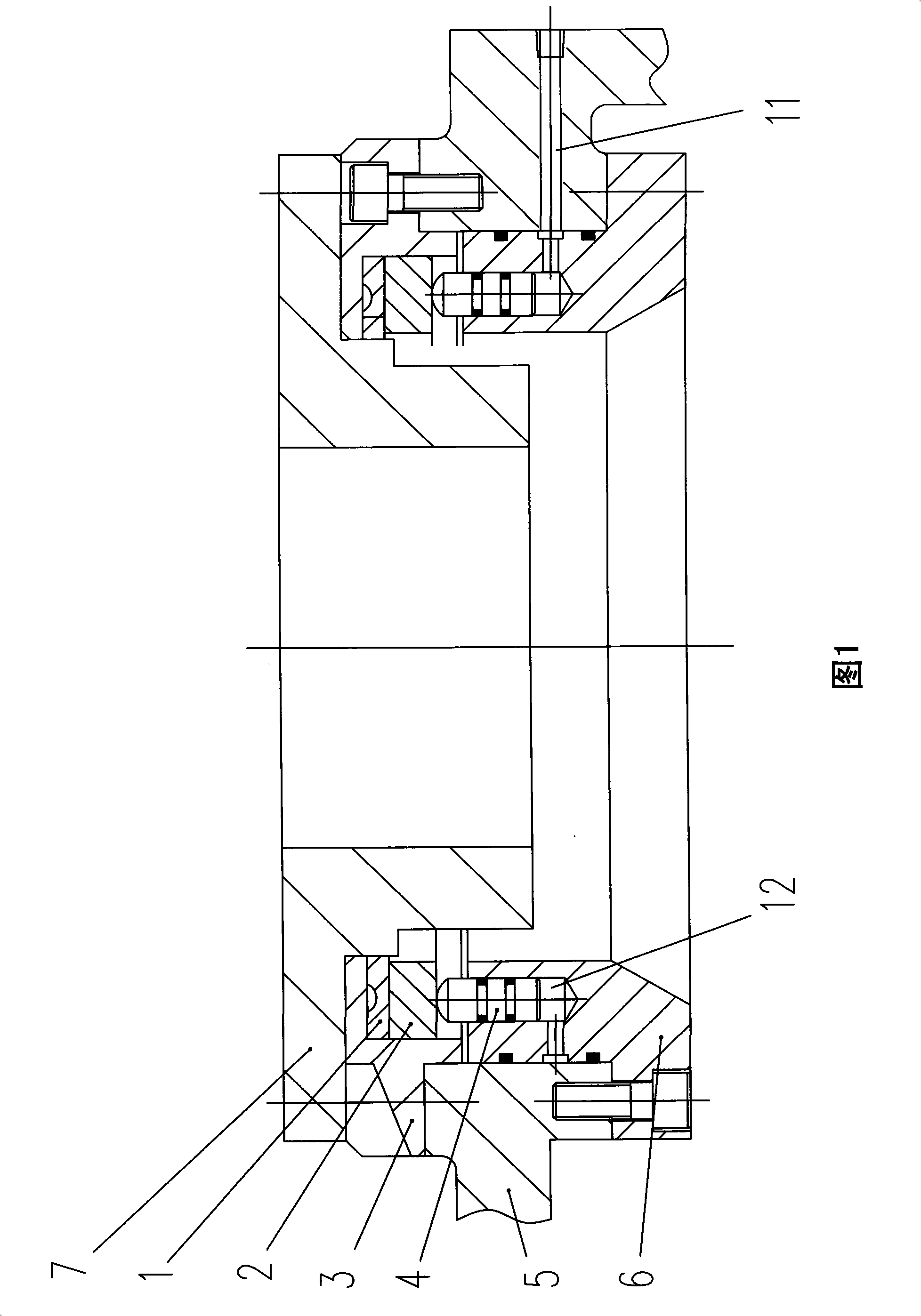
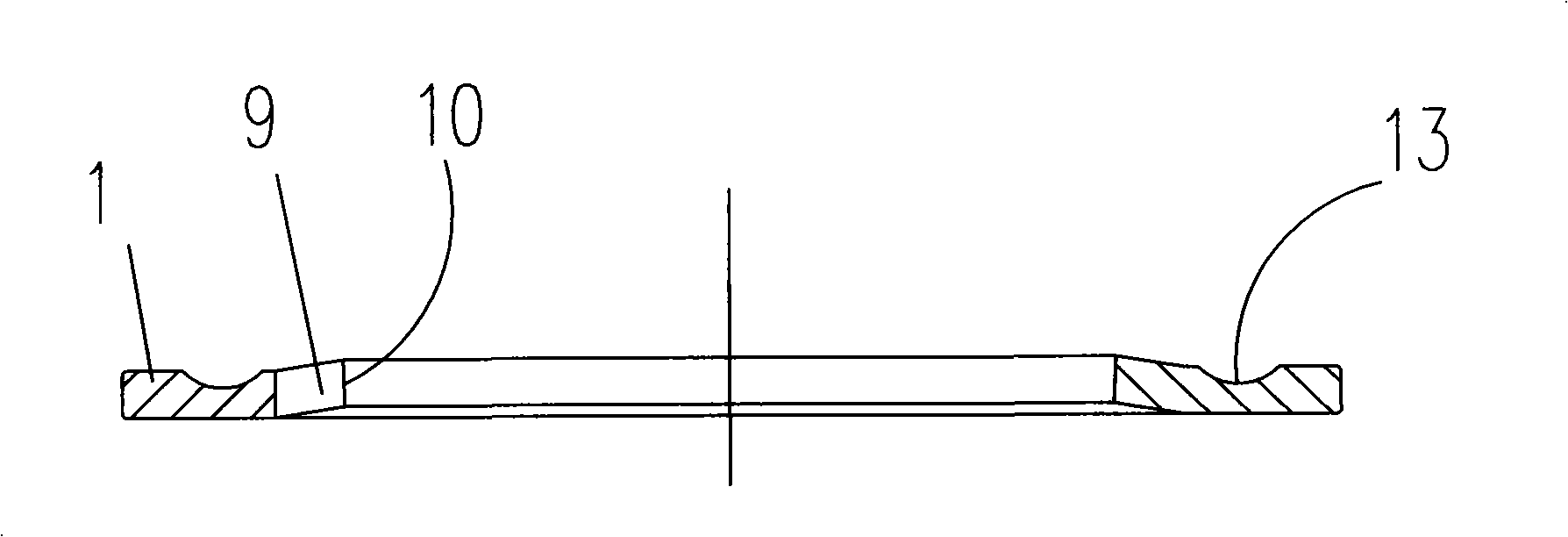
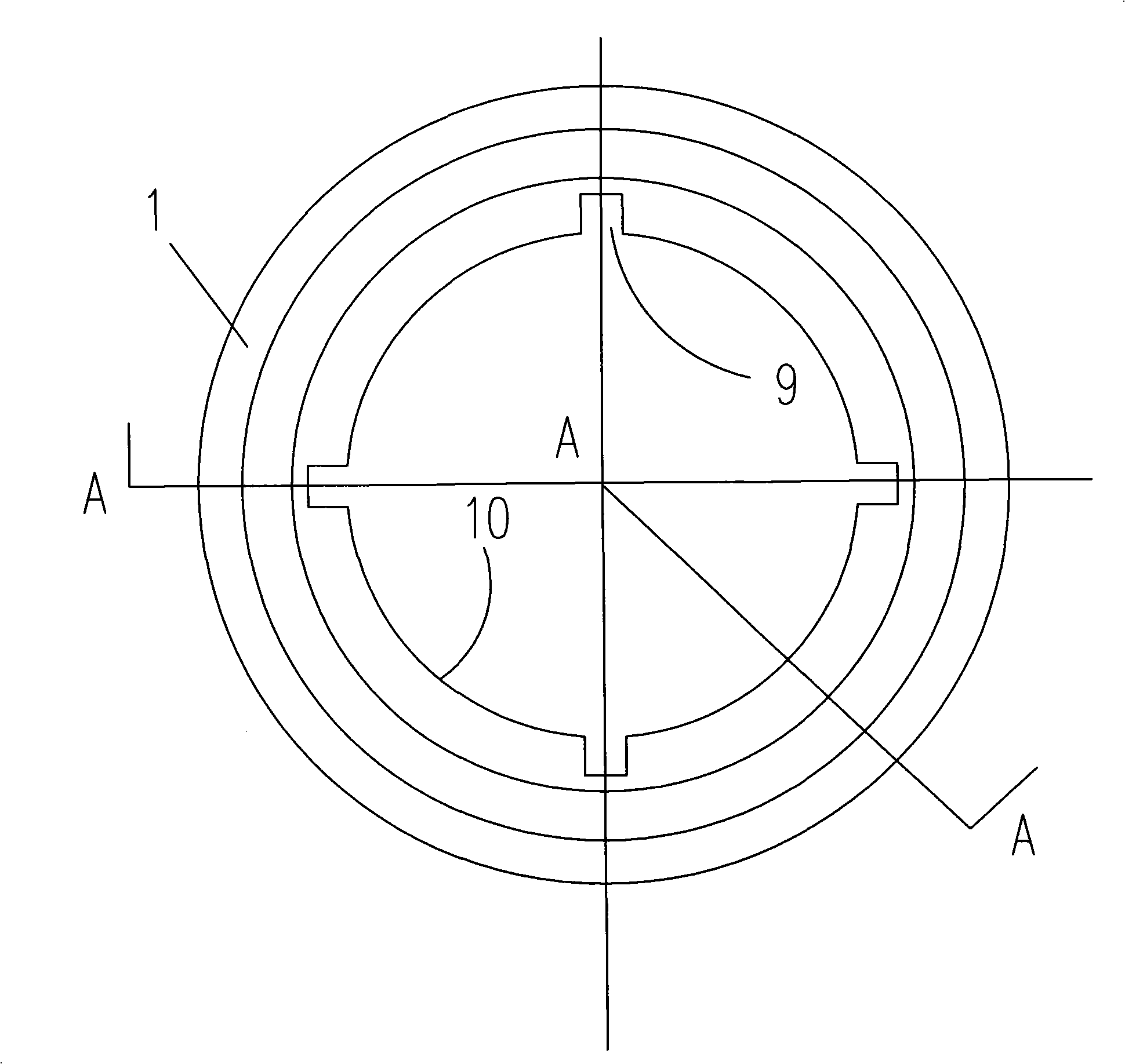
[0011] As shown in Figure 1: 5 is the clamp body, a plunger body 6 is arranged at the inner hole of the clamp body, and the plunger body 6 and the clamp body 5 are fixedly connected by bolts. A positioning disc 3 is fixedly connected with the clamp body 5 by bolts. A pressure plate 2 is installed inside the positioning plate 3 , and a radial elastic washer 1 is arranged between the pressure plate 2 and the end plate at the upper end surface of the positioning plate 3 . On the plunger body 6, there are plunger cavities 12 evenly distributed on the axial circumference, and the hydraulic plunger 4 is arranged in the plunger cavity 12. The upper end of the hydraulic plunger 4 matches the bottom surface of the pressure plate 2, so that Lean against the bottom surface of platen 2. An oil hole 11 communicating with the plunger cavity 12 is processed on the plunger body 6 and the clamp body 5 . During installation, the oil hole 11 is connected with the hydraulic control device throu...


PUM


Abstract

The invention discloses a clamping mechanism, in particular an outside centering and clamping mechanism for disc parts for machining equipment, which comprises a fixture body. The clamping mechanism is characterized in that a plunger body is arranged at an inner hole of the fixture body, and a positioning disc is arranged above the plunger body; a platen is arranged at an inner hole of the positioning disc, and a radial elastic washer is arranged between the platen and an upper endplate of the positioning disc; and the plunger body is provided with plunger chambers which are evenly distributedon the circumference and are communicated with an oil hole for oil input and output, the plunger chambers are internally provided with oil pressure plungers, and one end of each oil pressure plungeris matched with the platen. The clamping mechanism utilizes a hydraulic control device to drive the oil pressure plunger to press the radial elastic washer through the platen to make the radial elastic washer distort inward to clamp parts inside the radial elastic washer, can automatically center, ensure that the clamping force is not affected by human factors, has the advantages of flexible and reliable action, simple integral structure and easy operation, can eliminate the positioning gap of the parts at the same time, and improve the processing accuracy.

Description

technical field [0001] The invention relates to a clamping mechanism, in particular to an external centering clamping mechanism for disc parts on machining equipment. Background technique [0002] Disc parts also need a clamping device for clamping during machining. Most of the existing clamps for clamping such parts are chucks with jaws. It is troublesome, the clamping force is artificially large, and the reliability is poor. Contents of the invention [0003] The purpose of the present invention is to provide an external centering clamping mechanism for disk parts with simple overall structure, flexible and reliable action, automatic centering, elimination of part positioning gap and high processing precision, so as to overcome the shortcomings of the prior art. [0004] The outer centering clamping mechanism for disk parts of the present invention includes a clamp body 5, and is characterized in that: a plunger body 6 is provided at the inner hole of the clamp body 5, ...

Claims


Application Information

Patent Timeline
Patent Type & Authority Patents(China)
IPC IPC(8): B23Q3/06
Inventor 杨曙光吴长江陈永龙
Owner 大连机床(数控)股份有限公司
Learn More