Antitheft door lock

A technology of anti-theft door locks and main deadbolts, applied in building locks, locks with turning keys, buildings, etc., can solve the problems of easy forgetting, troublesome, unable to prevent thieves from robbing the door, and achieve convenient operation and improve safety. sexual effect

Inactive Publication Date: 2009-11-11
徐明达
View PDF0 Cites 4 Cited by
  • Summary
  • Abstract
  • Description
  • Claims
  • Application Information

AI Technical Summary

Problems solved by technology

From single bolt to multi-bolt, from single-direction locking to multi-directional locking, from single lock head to multi-lock head, its safety performance has been greatly improved, but there are still different degrees of cumbersome operation. For example: some indoor and outdoor locks and unlocks need to be operated with keys; some indoor locks and unlocks are manually operated with handles, and outdoor locks, unlocks, and external locks also need to be operated with keys; Thieves who came in through the window rushed out and had to use a key to lock the indoor manual opening handle; as for the anti-theft door lock with a fingerprint reader installed on one side, it could not prevent the thief who came in through the window from taking out the door
[0003] In the existing design, in order to prevent the indoor handle from opening the anti-theft lock when there is no one in the room, generally a key is used to lock the indoor handle opening mechanism outdoors, thereby preventing the intruder from opening the anti-theft lock through the indoor handle and escaping from the door. The mechanism needs to be operated with a key, which is troublesome and easy to forget

Method used


Image

  • Antitheft door lock
  • Antitheft door lock
  • Antitheft door lock

Examples


Embodiment Construction

[0031] The present invention will be further described in detail below in conjunction with the accompanying drawings and embodiments.

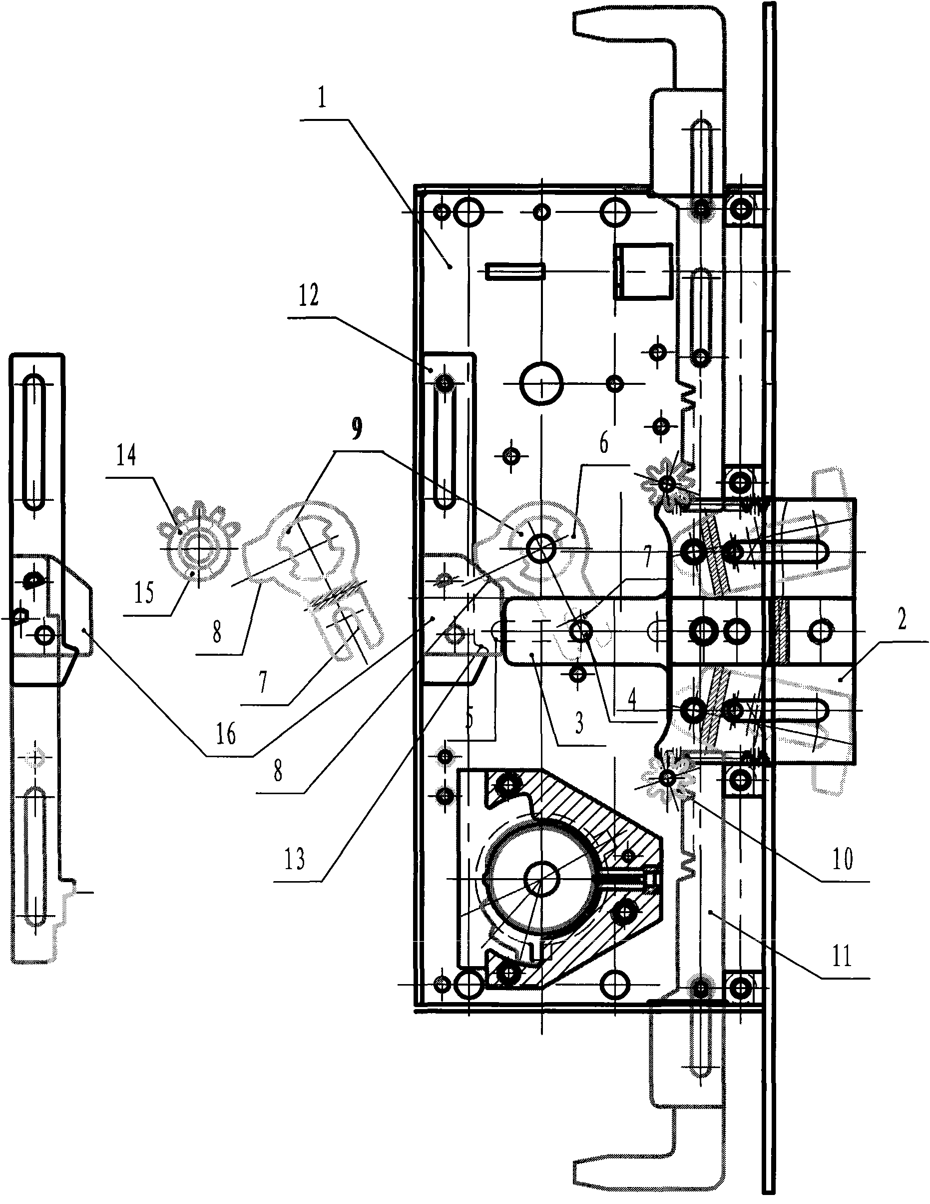
[0032] Main bolt mechanism see figure 1 A stepped pin 4 is arranged on the main deadbolt bar 3 of the main dead bolt 2, and the two ends of the stepped pin 4 are sleeved in the waist-type long groove 5 of the lock box 1 and the lock cover to move linearly, and the shaft hole of the swing bar 6 is provided with The fan-shaped hole 9 of two side symmetry is also set on the fan-shaped lug shaft 15 corresponding to it on the gear 14, and the fan-shaped angle on the fan-shaped lug shaft 15 is smaller than the fan-shaped angle on the fan-shaped hole 9. Small, swing bar 6 one ends with a U-shaped groove 7, groove 7 clamps the pin 4 on the main deadbolt bar 3, and the other end is provided with single-sided single-grain gear 8 and with the lower main clutch plate 12 The single-sided single-grain rack 13 is conditionally meshed, the fan-shaped protrus...


PUM


Abstract

An antitheft door lock comprises a main bolt mechanism, a key unlocking mechanism and a latch bolt unlocking mechanism, and is further provided with a manual locking mechanism; the manual locking mechanism comprises an outer half shaft, an inner half shaft, a master gear, a slave gear and indoor and outdoor handles; both the inner half shaft and the outer half shaft are installed as stepped shafts and divided into four parts: the outermost part are small cylinders respectively installed inside a lock box and a lock cover, chamfered edge cylinders are respectively fixedly bonded inside the outer half shaft and the inner half shaft, the biggest cylinders are all provided with sector grooves, smaller cylinders respectively installed on the front end are covered inside the master gear together, the outer half shaft of the most frontend extends out of the small cylinders, the inner half shaft is accessed in the small cylinder hole, and the outer half shaft and the inner half shaft are mutually assembled together through clearance fit; both sides of the central shaft hole of the master gear are provide with fixed blocks, and the lower end is provided with gear teeth and is meshed with the slave gear fixed by the swing link in the master bolt mechanism. The advantages are as follows: firstly, the operation is convenient, and the antitheft door lock can prevent a theft from opening the door and getting out after entering the room, thereby improving the security of the antitheft door lock; and secondly, the antitheft door lock prevents excessive external force from destroying the manual locking mechanism.

Description

technical field [0001] The invention relates to an anti-theft door lock. Background technique [0002] As a daily necessity, anti-theft door locks have undergone many developments. From single bolt to multi-bolt, from single-direction locking to multi-directional locking, from single lock head to multi-lock head, its safety performance has been greatly improved, but there are still different degrees of cumbersome operation. For example: some indoor and outdoor locks and unlocks need to be operated with keys; some indoor locks and unlocks are manually operated with handles, and outdoor locks, unlocks, and external locks also need to be operated with keys; The thief who came in through the window rushed out and had to use a key to lock the indoor manual opening handle; as for the anti-theft door lock with a fingerprint reader installed on one side, it could not prevent the thief who came in from the window from taking out the door. [0003] In the existing design, in order t...

Claims


Application Information

Patent Timeline
Patent Type & Authority Applications(China)
IPC IPC(8): E05B63/14E05B21/00
Inventor 徐明达
Owner 徐明达
Why Eureka
Try Eureka