Device and method for preparing transfer lubricant film on surfaces of ceramic balls
A technology for preparing devices and ceramic balls, which is applied in the direction of mechanical equipment, bearing components, shafts and bearings, etc., can solve the problems of weak bonding force and uneven coating of self-lubricating coatings, and achieve good bonding, uniform thickness, and good reduction The effect of rubbing
- Summary
- Abstract
- Description
- Claims
- Application Information
AI Technical Summary
Problems solved by technology
Method used
Image
Examples
specific Embodiment approach 1
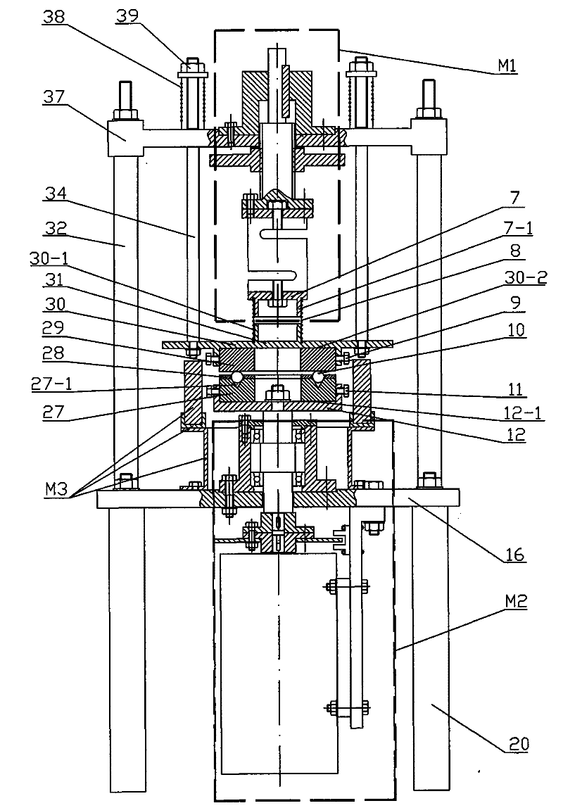
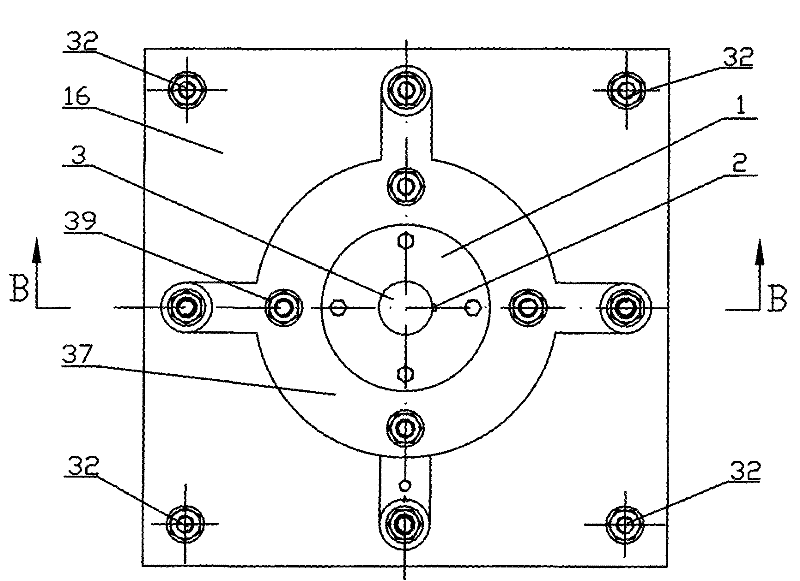
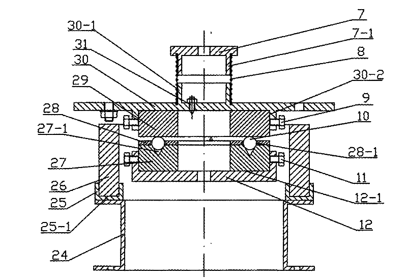
[0008] Specific implementation mode one: combine Figure 1 to Figure 5 Describe this embodiment, this embodiment consists of loading assembly M1, speed control assembly M2, heating assembly M3, first spring 8, four first positioning bolts 9, four second positioning bolts 11, lower grinding disc support 12. Base 16, four base pillars 20, lower grinding disc 27, cage 28, upper grinding disc 29, upper grinding disc support 30, temperature sensor 31, four bracket rods 32, four balance guide rods 34, bracket 37, four A second spring 38 and four compression nuts 39 are formed, four base pillars 20 are evenly distributed on the lower end surface of the base 16 and are fixedly connected with the base 16 by bolts, and four balance guide rods 34 are evenly distributed on the upper end surface of the base 16 And utilize the bolt and base 16 to be affixed, bracket 37 is installed on the upper end of four balance guide rods 34 and utilizes nut to fix the two, the center hole axis of bracke...
specific Embodiment approach 2
[0009] Specific implementation mode two: combination image 3 To illustrate this embodiment, the loading assembly M1 of this embodiment is composed of a guide sleeve 1, a guide key 2, a lead screw 3, a lead screw nut 4, a force sensor 6, a lower connection plate 7 and an upper connection plate 35, and the lead screw nut 4 Installed on the lead screw 3 and threaded, the guide sleeve 1 is installed on the upper end of the lead screw 3 through the guide key 2, the guide sleeve 1 is slidably connected with the lead screw 3, and the upper end surface of the upper connecting plate 35 is connected with the screw on the lead screw 3 by bolts. The lower end surface of the connector 3-1 is connected, the upper end of the force sensor 6 is connected with the upper connection plate 35 by bolts, and the lower end of the force sensor 6 is connected with the lower connection plate 7 by bolts. The lower end surface of the guide sleeve 1 is fixedly connected with the bracket 37. When the lead ...
specific Embodiment approach 3
[0010] Specific implementation mode three: combination image 3 Describe this embodiment, the speed control assembly M2 of this embodiment consists of an end cover 13, two bearings 14, a bearing seat 15, a speed signal receiver 17, a pulse signal generator 18, a motor support base 19, a motor 21, a shaft coupling The motor 21 is fixed on the motor support base 19, the output end of the motor 21 is connected with the input end of the transmission shaft 23 through the coupling 22, and the two bearings 14 are symmetrically arranged on the transmission shaft 23. At the two shaft shoulders, the bearing seat 15 is installed on the outer surface of the two bearings 14, the end cover 13 is installed on the transmission shaft 23 and connected with the upper end surface of the bearing seat 15 by bolts, and the pulse signal generator 18 is installed on the shaft coupling The speed signal receiver 17 is fixed on the motor support base 19 and is opposite to the pulse signal generator 18. ...
PUM
| Property | Measurement | Unit |
|---|---|---|
| diameter | aaaaa | aaaaa |
| diameter | aaaaa | aaaaa |
Abstract
Description
Claims
Application Information
 - R&D Engineer
- R&D Manager
- IP Professional
- Industry Leading Data Capabilities
- Powerful AI technology
- Patent DNA Extraction
Browse by: Latest US Patents, China's latest patents, Technical Efficacy Thesaurus, Application Domain, Technology Topic, Popular Technical Reports.
© 2024 PatSnap. All rights reserved.Legal|Privacy policy|Modern Slavery Act Transparency Statement|Sitemap|About US| Contact US: help@patsnap.com


