Spiral material quick auto transferring device

An automatic transfer, spiral technology, applied in the direction of furnace, furnace type, heat treatment equipment, etc., can solve the problems of high failure rate of parts, short life of mesh belt, impact of mesh belt, etc., and achieve the effect of reducing the failure rate

Active Publication Date: 2009-11-04
SUZHOU ZHONGMENZI IND FURNACE TECH CO LTD
View PDF0 Cites 0 Cited by
  • Summary
  • Abstract
  • Description
  • Claims
  • Application Information

AI Technical Summary

Problems solved by technology

However, due to the large drop of these parts and the considerable total weight, the falling parts will cause a certain impact on the mesh belt. The life of the mesh belt is generally very short, and if the parts are not hardened, the parts themselves will be deformed, etc. series of injuries
In addition, in some equipment, the buffer is increased by adding a flexible mechanism in the middle, but there is still a certain impact in this way
For rolling element parts, horizontal roller discharge has also appeared, but the drop is still very large, especially when the size of the part itself is large, the impact will be greater, which eventually leads to a generally high failure rate of the parts

Method used


Image

  • Spiral material quick auto transferring device

Examples


Embodiment Construction

[0016] A specific embodiment adopting the technical solution of the present invention will be listed below in conjunction with the accompanying drawings.

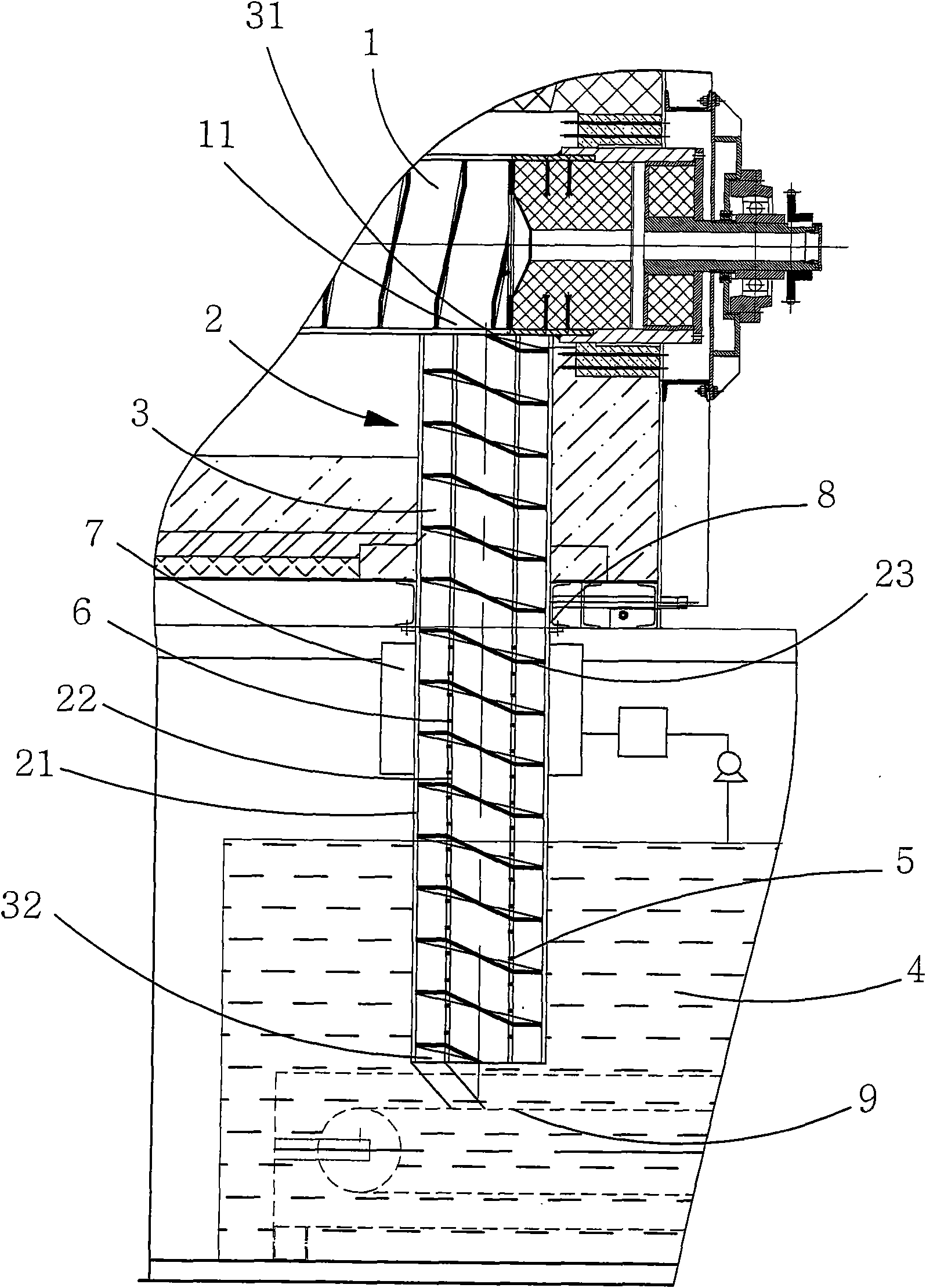
[0017] like figure 1 As shown in the material transfer device, the transfer device is for the heating furnace 1 above, and the heating furnace 1 has a discharge port 11, and the material guide cylinder 2 is connected below the discharge port 11. For the convenience of manufacture and installation, the material guiding cylinder 2 is arranged into upper and lower parts, and the upper and lower parts of the material guiding cylinder 2 are connected through a flange 8 which is completely airtight and smoothly transitioned. As shown in the figure, the upper material guide cylinder 2 is installed in the heating chamber of the heating furnace 1 . The lower part is located outside the furnace. The material guiding cylinder 2 itself is arranged vertically up and down. The material guide cylinder 2 specifically includes an outer c...


PUM


Abstract

The invention relates to a spiral material quick auto transferring device for material transferring of rolling element parts. The invention comprises a material guide barrel which is arranged along the up-down direction, a spiral channel which extends from top to bottom is arranged in the material guide barrel, an upper port and a lower port are position at the spiral channel, the upper port is communicated with a discharge hole of a heating furnace, the lower port of the spiral channel is introduced into an oil sink, the rolling element parts are sent to the spiral channel from the discharge hole and then are sent to the oil sink in a sliding way from the lower port of the spiral channel. By arranging the up-down spiral channel, no external force is needed for introducing parts to discharge from up to down, the quick auto transferring is realized by the gravity of the devices and a helix angle, by transferring with the device, the impact force after falling down of the material is effectively controlled and the fraction defective is reduced.

Description

technical field [0001] The invention relates to a heat treatment discharge equipment, in particular to a spiral material fast automatic transfer device for rolling element parts, which can realize fast automatic transfer of parts from the heating furnace of the heat treatment equipment to the cooling medium. Background technique [0002] In the traditional process, the parts are quenched directly from the furnace into a tank (such as an oil tank) filled with a cooling medium or sprayed with a cooling medium during the falling process. Regardless of which of the above methods is used for quenching, the drop of parts falling is relatively large. If the depth of the quenching tank is not enough, and the parts do not have enough cushioning, the parts are easily damaged when they fall into the tank. For this reason, on some equipments on the market at present, by adding net bag in oil tank, to increase cushioning. However, due to the large drop of these parts and the considerab...

Claims


Application Information

Patent Timeline
Patent Type & Authority Applications(China)
IPC IPC(8): C21D9/00
Inventor 蒋明根王彦荣宋思科
Owner SUZHOU ZHONGMENZI IND FURNACE TECH CO LTD
Why Eureka
Try Eureka