
Phase-locking amplifier

A lock-in amplifier and phase-shifting technology, applied in amplifiers, parametric amplifiers, amplifier types, etc., can solve the problems of insufficient phase noise, large phase noise, inconvenience, etc., and achieve the effect of improving phase resolution

Active Publication Date: 2009-10-21
SHANGHAI MICRO ELECTRONICS EQUIP (GRP) CO LTD
View PDF0 Cites 10 Cited by
  • Summary
  • Abstract
  • Description
  • Claims
  • Application Information

AI Technical Summary

Problems solved by technology

[0005] Most of the current analog lock-in amplifiers use the method of changing the resistance value of the reference signal trigger circuit to adjust the reference signal phase, which is inconvenient and has large phase noise; while the reference signal processing unit of most digital lock-in amplifiers uses digital reference Phase shift is realized, although the phase resolution can reach the millidegree level, the phase accuracy is mostly 0.01 degrees
But in measurement systems where phase noise is extremely demanding, such phase noise is not sufficient

Method used


Image

  • Phase-locking amplifier
  • Phase-locking amplifier
  • Phase-locking amplifier

Examples


Embodiment Construction

[0034] The lock-in amplifier of the present invention will be described below in conjunction with the accompanying drawings and specific embodiments.

[0035] The reference signal in the present invention can be selected from various signals, such as square wave, sine wave, triangle wave, ramp wave, etc. In this embodiment, the reference signal is selected as a 4KHZ square wave.

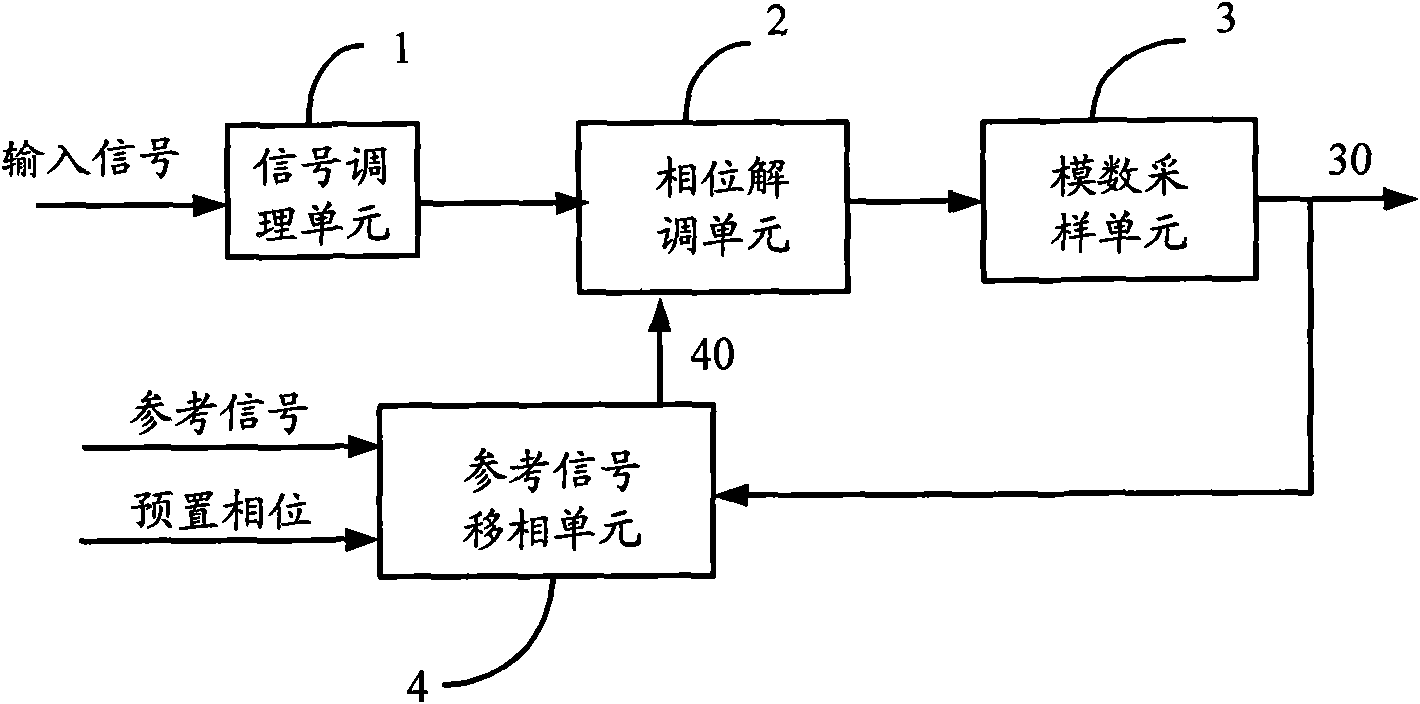
[0036] see figure 1 , figure 1 It is a schematic structural diagram of a lock-in amplifier according to an embodiment of the present invention. The lock-in amplifier includes: a signal conditioning unit 1, a phase demodulation unit 2, an analog-to-digital sampling unit 3, and a reference signal phase shifting unit 4, wherein,

[0037] The input terminal of the signal conditioning unit 1 is connected to the input signal, and the output terminal is connected to the input terminal of the phase demodulation unit 2 for inverting, filtering and dividing the input signal. The signal conditioning unit 1 ca...


PUM


Abstract

The invention provides a phase-locking amplifier, which comprises a signal conditioning unit, a phase demodulation unit and a digital-analog sampling unit, wherein the signal conditioning unit performs phase reversion, filtering and pressure partition on an input signal to be detected; the phase demodulation unit multiplies signals output by the signal conditioning unit and a reference signal phase-shifting unit; and the digital-analog sampling unit performs digital-analog conversion on the signal output by the phase demodulation unit to obtain a digital signal and feeds the digital signal back to the reference signal phase-shifting unit. The phase-locking amplifier also comprises the reference signal phase-shifting unit which is used for adjusting the phase of an input reference signal according to the digital signal fed back by the digital-analog sampling unit. Compared with the prior phase-locking amplifier, the phase-locking amplifier provided by the invention is provided with the reference signal phase-shifting unit to count the input reference signals simultaneously according to different phase clocks, thus the phase resolution is multiplied.

Description

technical field [0001] The invention relates to a weak signal detection instrument, in particular to a lock-in amplifier. Background technique [0002] When detecting a weak signal to be tested, useless noise and interference always appear, which affects the accuracy and sensitivity of the measurement, especially when the noise power exceeds the power of the signal to be tested, it is necessary to use a weak signal Detection instruments and equipment to recover or detect the original signal. The invention of the lock-in amplifier (Lock-in Amplifier, referred to as LIA) has made a breakthrough in weak signal detection technology, which has greatly promoted the development of basic science and engineering technology. [0003] The lock-in amplifier is based on coherent detection technology, mainly including signal channel, reference channel and correlator. Early lock-in amplifiers were realized by analog circuits. With the development of digital technology, lock-in amplifiers...

Claims


Application Information

Patent Timeline
IPC IPC(8): H03F7/00H03L7/00
Inventor 李志强潘炼东
Owner SHANGHAI MICRO ELECTRONICS EQUIP (GRP) CO LTD
Learn More