Large vacuum coating equipment
A vacuum coating and equipment technology, applied in vacuum evaporation coating, sputtering coating, gaseous chemical coating, etc., can solve the problems of poor product quality and high production cost, and achieve equipment cost saving, quality improvement, and shortening of rough pumping the effect of time
- Summary
- Abstract
- Description
- Claims
- Application Information
AI Technical Summary
Problems solved by technology
Method used
Image
Examples
Embodiment 1
[0026] This embodiment has the following advantages:
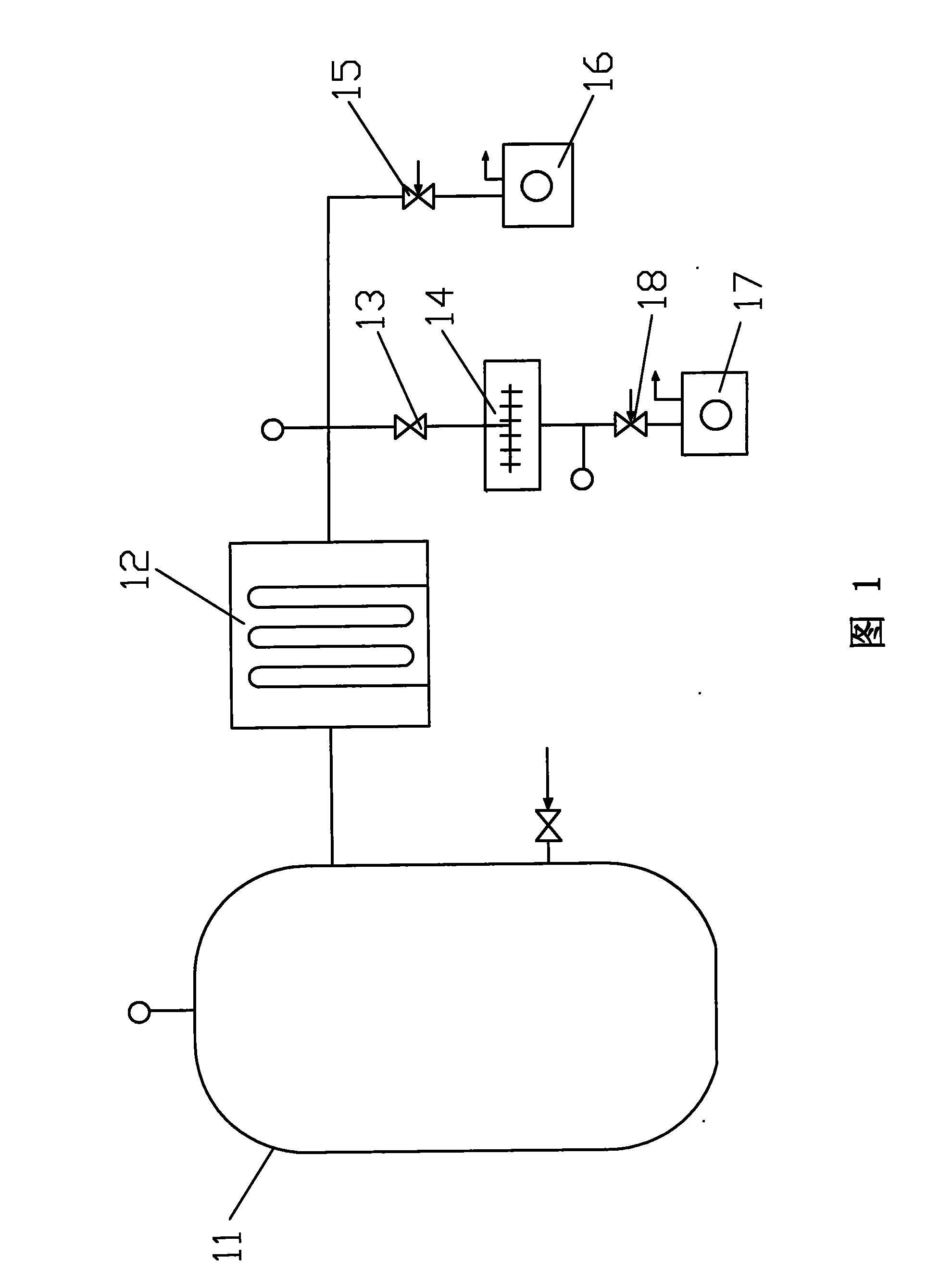
[0027] (1) In this embodiment, the traction molecular pump 14 and the water vapor pump 12 are used to replace the oil diffusion pump and Roots pump of the traditional coating equipment, so as to save 80% of energy consumption for pumping, improve the efficiency of vacuum coating, and improve the quality of coating products.
[0028] (2) The water vapor pump 12 does not need a backing pump, and the traction molecular pump 14 only needs to adopt the backing pump 17 of low pumping speed; therefore, the rough pump 16 is separated from the backing pump 17, and the traction molecular pump 14 adopts a dedicated backing pump 17, which can further save energy consumption.
[0029] (3) The working time of the rough pump 16 provided in this embodiment is very short, therefore, one rough pump 16 can be shared by multiple coating equipment, saving equipment cost and floor space.
[0030] (4) The coating chamber 11 is directly connecte...
Embodiment 2
[0035] Embodiment 3. Double-chamber winding large-scale vacuum coating equipment
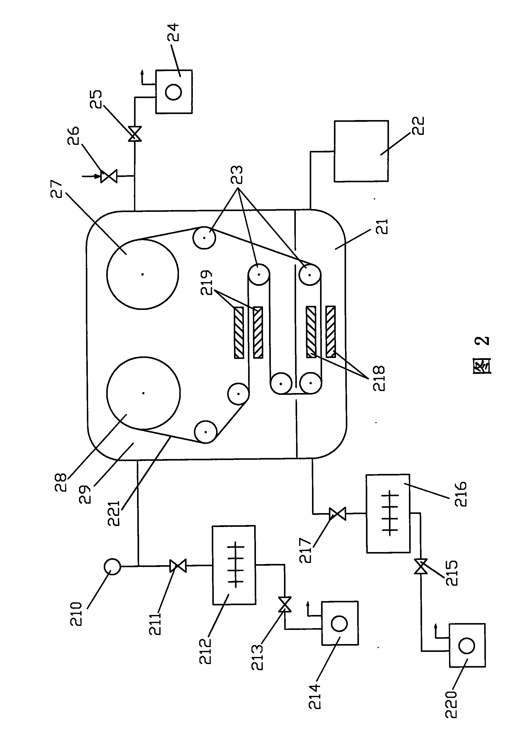
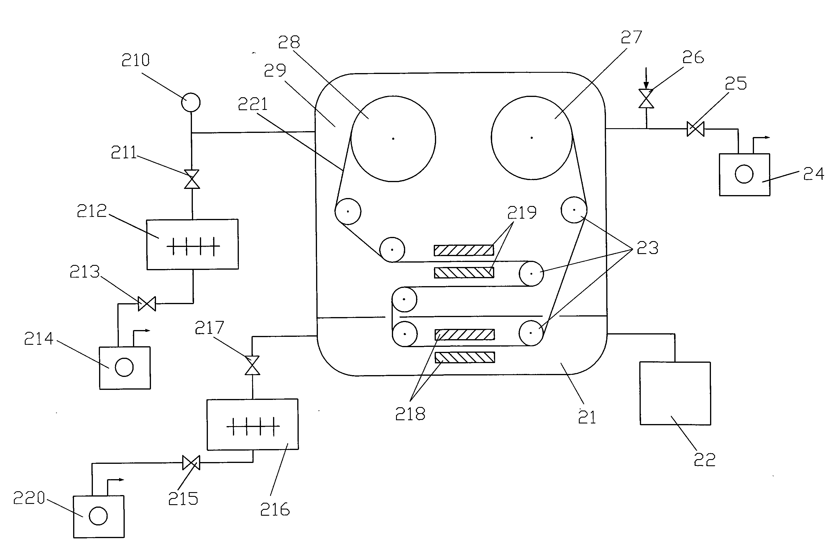
[0036] This example figure 2 As shown, the coating equipment is composed of a winding chamber 29 and a coating chamber 21; one end of the winding chamber 29 communicates with the drag molecular pump 212 through a vacuum valve 211, and the drag molecular pump 212 communicates with the drag molecular pump 213 through a vacuum valve 213. The backing pump 214 communicates; the other end of the winding chamber 29 communicates with the rough pump 24 through a vacuum valve 25; the coating chamber 21 communicates with another traction molecular pump 216 through a vacuum valve 217, the traction The molecular pump 216 communicates with another backing pump 220 through a vacuum valve 215; the other end of the coating chamber 21 directly communicates with the water vapor pump 22; the coating chamber 21 is provided with a magnetron sputtering target 218.
Embodiment 3
[0037] In addition, the winding chamber 29 is also communicated with the intake valve 26 and the vacuum gauge 210; the winding chamber 29 is also provided with a feeding reel 28 and a receiving reel 27, and the film to be coated 221 is sleeved on On the feeding reel 28, guide through the roller 23, pass through the narrow slit, and carry out coating through the magnetron sputtering target 218, after the coating is completed, guide through the roller 23, pass through the narrow slit, and the material receiving The reel 27 is collected; the winding chamber 29 is also provided with a pair of glow discharge electrodes 219 that can perform glow cleaning and degassing on the film 221 to be coated before coating.
[0038] The operation steps of this embodiment are as follows:
[0039] (1) film to be coated 221 is installed in winding chamber 29 and coating chamber 21, then, close winding chamber 29 and coating chamber 21;
[0040] (2) close intake valve 26, vacuum valve 25, vacuum v...
PUM
 Abstract
Description
Claims
Application Information
 - R&D
- Intellectual Property
- Life Sciences
- Materials
- Tech Scout
- Unparalleled Data Quality
- Higher Quality Content
- 60% Fewer Hallucinations
Browse by: Latest US Patents, China's latest patents, Technical Efficacy Thesaurus, Application Domain, Technology Topic, Popular Technical Reports.
© 2025 PatSnap. All rights reserved.Legal|Privacy policy|Modern Slavery Act Transparency Statement|Sitemap|About US| Contact US: help@patsnap.com


