Low-carbon, oil-free high-speed vacuum pumping unit
A vacuum pumping and unit technology, applied in vacuum evaporation coating, mechanical equipment, machine/engine, etc., can solve the problems of serious oil vapor pollution, high power consumption, high energy consumption, eliminate oil vapor pollution, reduce pumping The effect of reducing gas energy consumption and improving the quality of vacuum products
- Summary
- Abstract
- Description
- Claims
- Application Information
AI Technical Summary
Problems solved by technology
Method used
Image
Examples
Embodiment 1
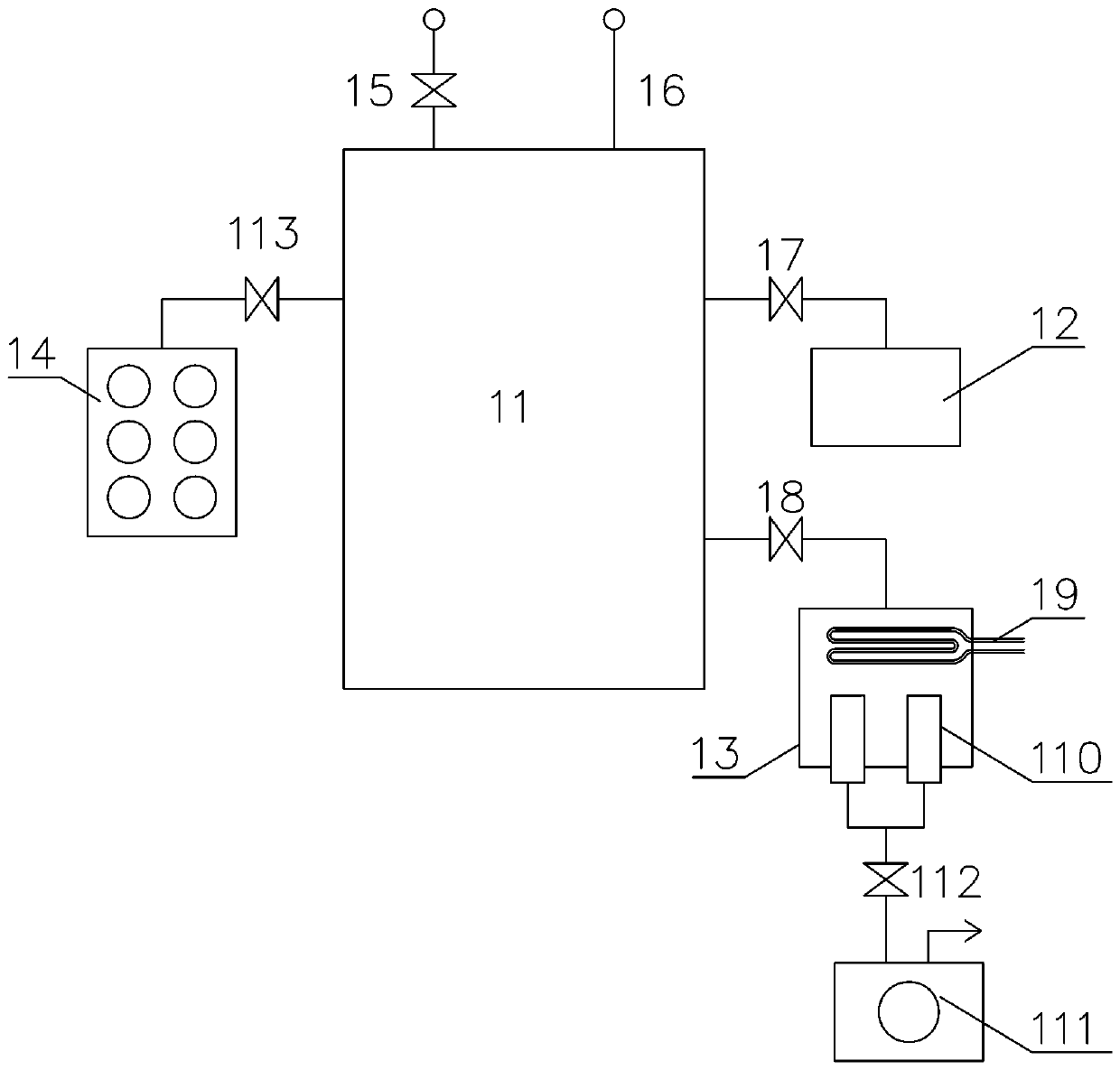
[0026] Embodiment 1: A low-carbon, oil-free high-speed vacuum pumping unit assembled in two vacuum housings by an oil-free vacuum pump
[0027] Such as figure 1 As shown, a low-carbon, oil-free and high-speed vacuum pumping unit provided in Embodiment 1 of the present invention includes a vacuum chamber 11, and the vacuum chamber 11 is connected with a rough pump unit 12, a vacuum housing 13, and a chemical adsorption pump unit respectively. 14. The purge valve 15 is connected to the vacuum gauge 16, a first vacuum valve 17 is provided between the vacuum chamber 11 and the roughing pump unit 12, a second vacuum valve 18 is provided between the vacuum chamber 11 and the vacuum housing 13, and the vacuum A cryogenic water vapor pump 19 is arranged above the inside of the housing 13, and a radial flow pump unit 110 is arranged at the bottom of the inside of the vacuum housing 13. The exhaust port is connected to the backing pump 111 through the third vacuum valve 112. A fourth v...
Embodiment 2
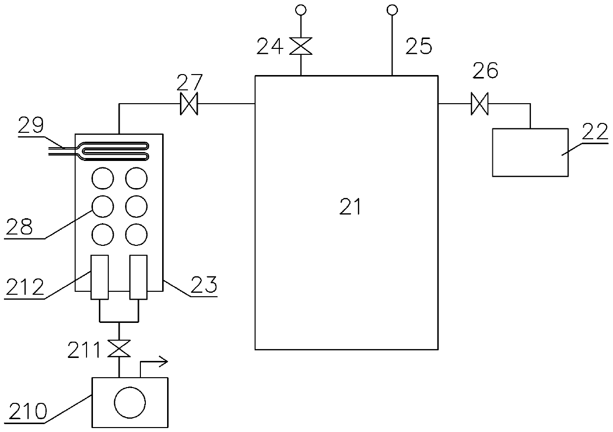
[0041] Embodiment 2 A low-carbon, oil-free, high-speed vacuum pumping unit assembled in the same vacuum housing by an oil-free vacuum pump
[0042] Such as figure 2 As shown, a low-carbon, oil-free and high-speed vacuum pumping unit provided in Embodiment 2 of the present invention includes a vacuum chamber 21, and the vacuum chamber 21 is connected with a rough pump unit 22, a vacuum housing 23, and an air release valve 24 respectively. It is connected with the vacuum gauge 25, a first vacuum valve 26 is provided between the vacuum chamber 21 and the roughing pump unit 22, a second vacuum valve 27 is provided between the vacuum chamber 21 and the vacuum housing 23, and the vacuum housing 23 is provided by the following A radial flow pump unit 212, a chemical adsorption pump unit 28, and a cryogenic water vapor pump 29 are provided in sequence upwardly. The radial flow pump unit 212 is composed of four radial flow pumps connected in parallel for pumping air. Each radial flow ...
Embodiment 3
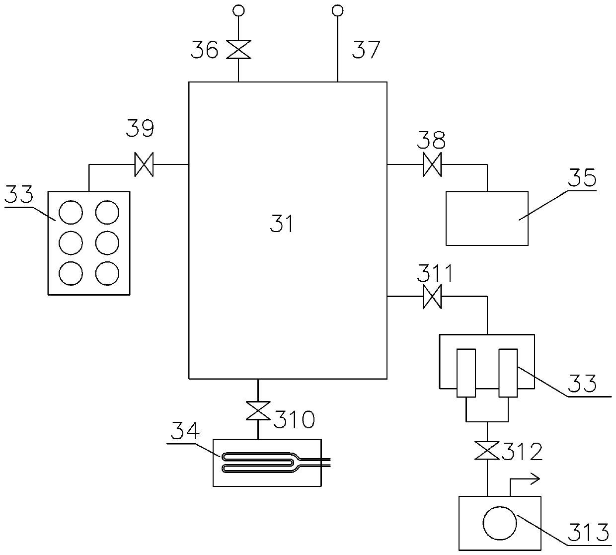
[0055] Embodiment 3 Oil-free vacuum pump sets are respectively installed in a vacuum housing, low-carbon, oil-free high-speed vacuum pumping unit
[0056] Such as image 3 As shown, a low-carbon, oil-free high-speed vacuum pumping unit provided in Embodiment 3 of the present invention includes a vacuum chamber 31, and the vacuum chamber 31 is connected with a rough pump unit 32, a chemical adsorption pump unit 33, and a cryogenic water vapor pump unit respectively. Pump 34, radial flow pump unit 35, air release valve 36 and vacuum gauge 37 are connected, a first vacuum valve 38 is provided between the vacuum chamber 31 and the rough pump unit 32, and a first vacuum valve 38 is provided between the vacuum chamber 31 and the chemical adsorption pump unit 33. The second vacuum valve 39, the third vacuum valve 310 is arranged between the vacuum chamber 31 and the cryogenic water vapor pump 34, the fourth vacuum valve 311 is arranged between the vacuum chamber 11 and the radial flo...
PUM
 Abstract
Description
Claims
Application Information
 - R&D
- Intellectual Property
- Life Sciences
- Materials
- Tech Scout
- Unparalleled Data Quality
- Higher Quality Content
- 60% Fewer Hallucinations
Browse by: Latest US Patents, China's latest patents, Technical Efficacy Thesaurus, Application Domain, Technology Topic, Popular Technical Reports.
© 2025 PatSnap. All rights reserved.Legal|Privacy policy|Modern Slavery Act Transparency Statement|Sitemap|About US| Contact US: help@patsnap.com


