
Valve apparatus of shock absorber

A valve device and shock absorber technology, applied in shock absorbers, springs/shock absorbers, shock absorbers, etc., can solve the problems of difficult control of damping force characteristics.

Inactive Publication Date: 2009-10-14
HL MANDO CORP
View PDF0 Cites 6 Cited by
  • Summary
  • Abstract
  • Description
  • Claims
  • Application Information

AI Technical Summary

Problems solved by technology

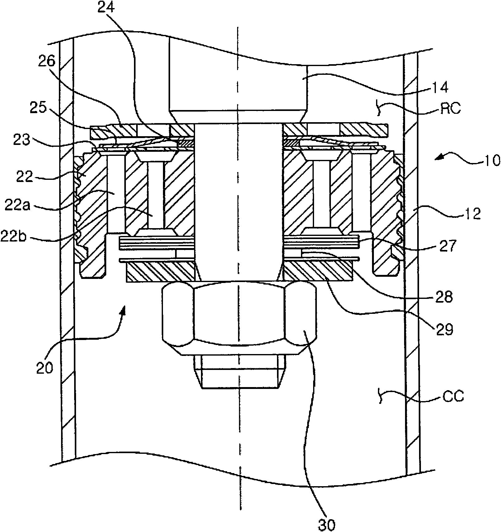
However, when the outer diameter of the valve disc 27 is reduced, a problem arises that the damping force characteristics are not easily controlled at low speeds.

Method used


Image

  • Valve apparatus of shock absorber
  • Valve apparatus of shock absorber
  • Valve apparatus of shock absorber

Examples


Embodiment Construction

[0019] Exemplary embodiments will now be described in detail with reference to the accompanying drawings.

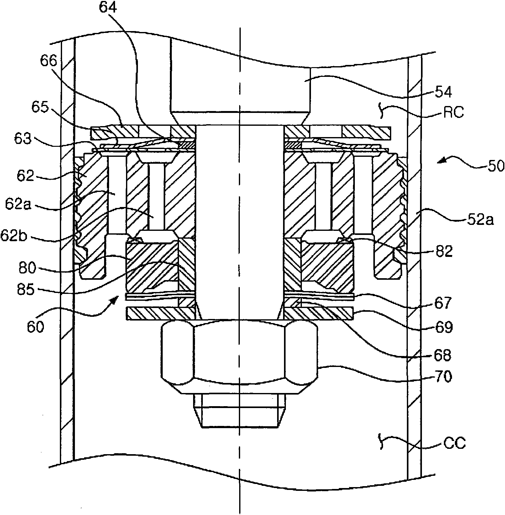
[0020] figure 2 is a cross-sectional view of a shock absorber according to an embodiment of the present invention, image 3 is a cross-sectional view of a valve device of a shock absorber according to one embodiment of the present invention.

[0021] exist figure 2 and 3 Among them, a shock absorber 50 according to one embodiment includes a cylinder 52 connected to a wheel side of a vehicle, and a piston rod 54 connected to a vehicle body side. Here, the cylinder 52 may have a double pipe structure including an inner pipe 52a and an outer pipe 52b, or have a single pipe structure.

[0022] The piston rod 54 is disposed in the cylinder 52 and reciprocates therein, and includes a valve device 60 incorporated at one end of the piston rod 54 and dividing the interior of the cylinder 52 into a compression chamber CC and a rebound chamber RC.

[0023] The valve device 6...


PUM


Abstract

A valve apparatus of a shock absorber is provided to a piston rod of the shock absorber and generates a damping force by controlling a fluid flow between a rebound chamber and a compression chamber. A valve apparatus for a shock absorber includes a piston valve having rebound and compression passages, a sliding valve movably coupled to a piston rod to block and open the rebound passages, and at least one valve disc provided at a lower side of the sliding valve and separated a predetermined distance from a washer by a retainer. The valve disc can be bent while resiliently supporting an outer periphery of the sliding valve. The valve disc has an increased size, so that easy control of a damping force at low speed and a gradual increase of the damping force even at high speed can be obtained by the shock absorber having a decreased size.

Description

technical field [0001] The present invention relates to a valve device mounted on a shock absorber to generate a damping force, and more particularly to a valve device of a shock absorber which improves the mounting structure of a valve disc on a piston for generating a damping force. Background technique [0002] Typically, vehicles are equipped with a suspension system to improve ride comfort by cushioning shocks or vibrations transmitted from the road to the axles during driving. One component that makes up a suspension system is the shock absorber. The shock absorber is arranged between the axle and the vehicle body, and includes a cylinder and a piston rod reciprocating in the cylinder. The cylinder is filled with working fluid, such as gas or oil, which are driven by a piston valve fixed on one end of the piston rod to generate damping force. [0003] figure 1 is a cross-sectional view of the valve arrangement of a conventional shock absorber. see figure 1 , the s...

Claims


Application Information

Patent Timeline
Patent Type & Authority Applications(China)
IPC IPC(8): F16F9/34
CPCF16F9/3485F16F9/34
Inventor 金泓植
Owner HL MANDO CORP
Learn More