
Energy distributor

An energy distributor and contactor technology, which is applied in the direction of current collectors, secondary battery charging/discharging, electric vehicles, etc., to ensure safe access, eliminate impact effects, and ensure safe use.

Inactive Publication Date: 2009-10-14
CITIC GUOAN MENGGULI NEW ENERGY TECH
View PDF0 Cites 6 Cited by
  • Summary
  • Abstract
  • Description
  • Claims
  • Application Information

AI Technical Summary

Problems solved by technology

[0003] Due to multiple power sources, hybrid electric vehicles need an energy distribution device that can safely, reliably and accurately distribute energy and control energy flow, but there is no dedicated energy distribution device on the market at present

Method used


Image

  • Energy distributor
  • Energy distributor
  • Energy distributor

Examples


Embodiment

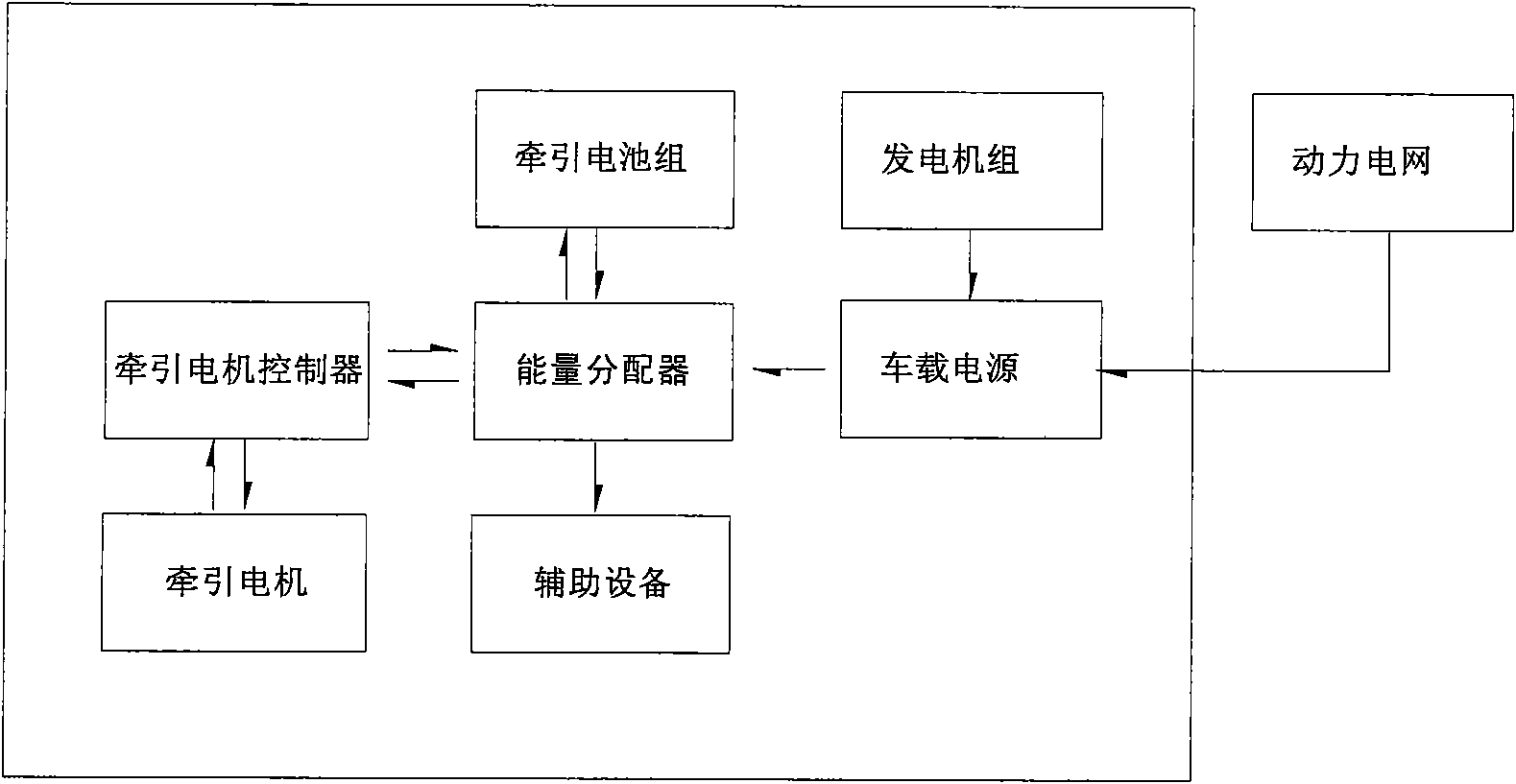
[0049] The energy distributor of this embodiment is connected between the energy supply equipment and the traction motor of the electric vehicle. The input connection terminals of the energy distributor are respectively connected to the traction generator set and the traction battery pack in the working state; and are connected to the grid when the grid is connected to the grid for charging. The output connection terminals are connected to the traction motor controller and auxiliary equipment, such as figure 2 shown.

[0050] The main functions of this embodiment include: power grid input control, electric energy output control of generator sets, energy storage control of traction batteries, energy release control of traction battery packs, braking kinetic energy recovery control and alarm output control.

[0051] The energy distributor of this embodiment includes a main body and peripheral parts. The main part and the peripheral parts are described respectively below.

[...


PUM


Abstract

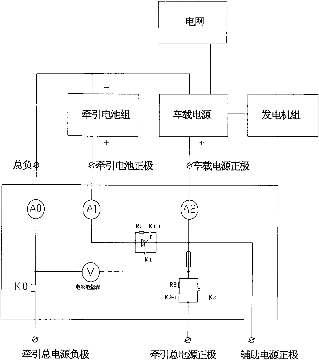
The invention provides an energy distributor used for a hybrid electric vehicle. The energy distributor is equipment for effectively controlling an energy flow direction and an energy distributing mode among a traction generator set, a traction battery set and a traction motor and comprises an executive part, a control part and a display part, wherein the executive part is respectively connected with the traction generator set, the traction battery set and a traction motor controller to form a charging and discharging control loop of the traction battery set; the executive part controls the charging and discharging loop of the traction battery set by controlled silicon and a DC contactor which are connected in parallel; and the executive part is driven by the control part. The invention can well prevent an over-charging phenomenon of the battery set and can ensure that a grid is safely accessed during charge, the generator set is safely used, each power battery is operated in a safe tolerance and electric equipment energy is supplied.

Description

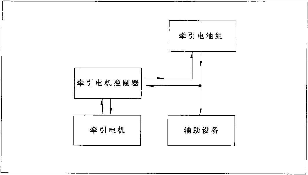
technical field [0001] The present invention relates to an automatic control system, and in particular, the present invention relates to a device for controlling the energy flow direction and energy distribution mode between a traction battery pack and a traction motor for a hybrid electric vehicle. Background technique [0002] At present, there are mainly two basic structures of the energy supply system of electric vehicles: one is pure electric vehicles. Such as figure 1 As shown, this vehicle uses the power grid to charge the on-board traction battery pack, and uses the energy stored in the traction battery pack to maintain the vehicle. Energy from the traction battery is output directly to the traction motor controller and auxiliary equipment. The main features of this vehicle are long energy storage time (charging time) and short continuous mileage, and can only be used for fixed bus lines or short-distance environments. The other is a hybrid electric vehicle. and ...

Claims


Application Information

Patent Timeline
IPC IPC(8): B60L3/00B60K6/22H02J7/00H01M10/44
CPCY02E60/12Y02E60/10
Inventor 其鲁毛永志罗洪旭
Owner CITIC GUOAN MENGGULI NEW ENERGY TECH
Learn More