
Electric video laryngoscope

A video and electronic technology, applied in the field of electronic video laryngoscope, can solve the problems of shortening the length of the handle, convenient operation, high requirements for doctors' operating experience, inconvenient operation, etc., and achieves adjustable viewing angle and low operating experience requirements. , the effect of convenient operation

Inactive Publication Date: 2009-10-14
石学银 +1
View PDF3 Cites 0 Cited by
  • Summary
  • Abstract
  • Description
  • Claims
  • Application Information

AI Technical Summary

Problems solved by technology

[0006] In order to overcome the shortcomings of the existing video laryngoscopes, such as long handle, inconvenient operation, and high requirements for doctors' operating experience, the present invention provides a visual laryngoscope that can effectively shorten the length of the handle, is easy to operate, and requires less operating experience for doctors. Electronic video laryngoscope

Method used


Image

  • Electric video laryngoscope
  • Electric video laryngoscope
  • Electric video laryngoscope

Examples


Embodiment Construction

[0031] The present invention will be further described below in conjunction with the accompanying drawings.

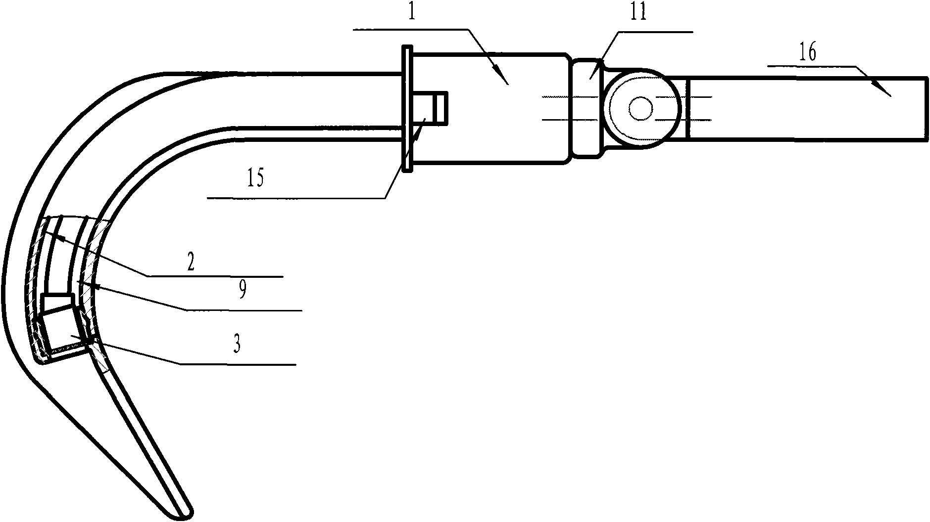
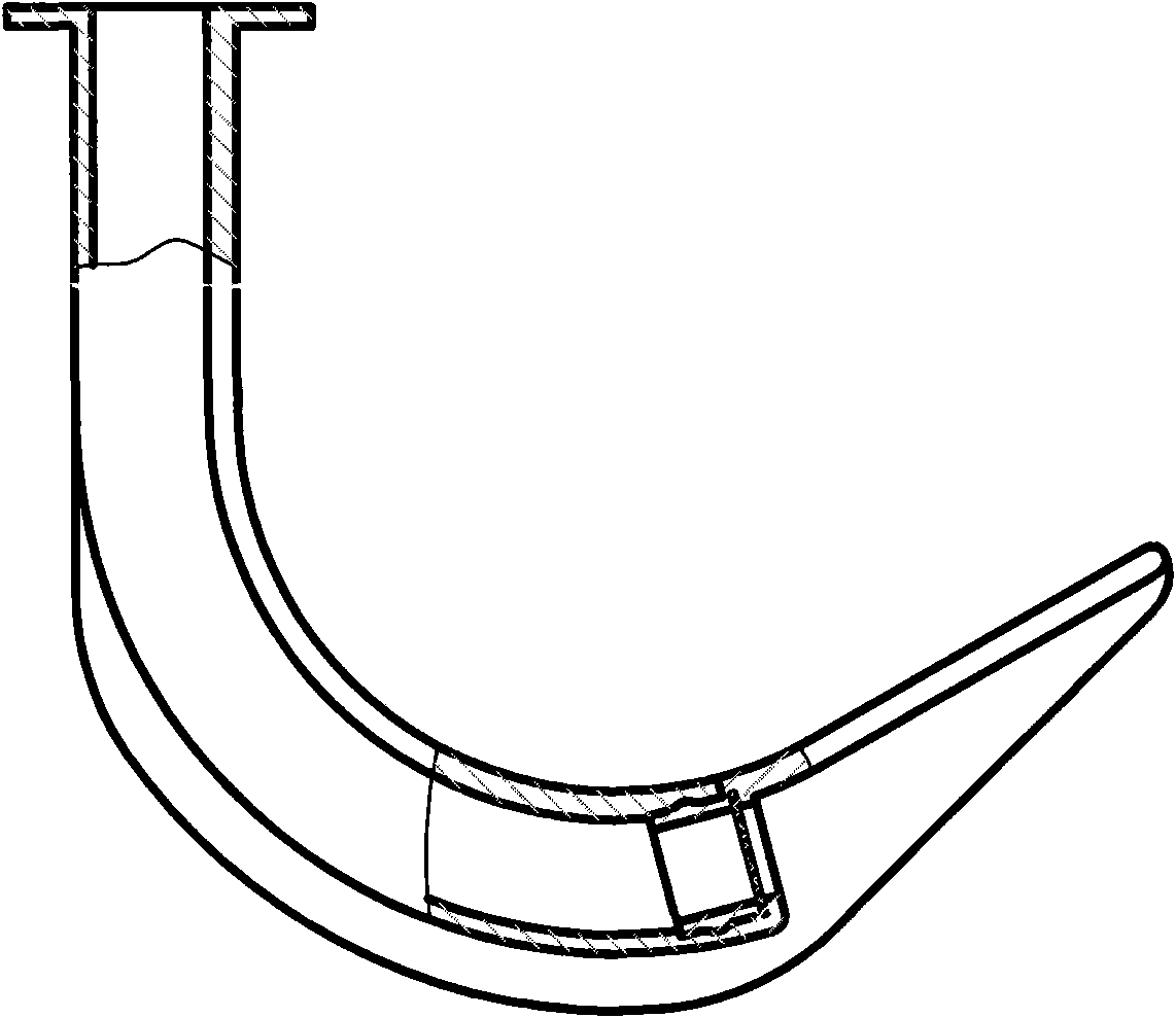
[0032] refer to Figure 1 to Figure 11 , an electronic video laryngoscope, comprising a bracket assembly 1, an arc-shaped oropharyngeal airway and a tongue depressor assembly 2, a camera assembly 3, a battery box 4 and a display 5, the arc-shaped oropharyngeal airway and a tongue depressor The board assembly 2 is located at the front end of the bracket assembly 1, the camera assembly 3 is located at the lower part of the curved oropharyngeal airway and the tongue depressor plate assembly 2, the camera assembly 3 includes a camera and a lighting lamp, and the display 5 can Rotately installed on the bracket assembly 1, the camera is connected with the display 5 through a data line, the battery box 4 is connected with the lighting lamp, the camera and the display 5 through a wire, and the electronic video multifunctional laryngoscope also includes a The battery case 6 is...


PUM


Abstract

The invention provides an electronic video laryngoscope. The laryngoscope comprises a bracket component, an arc oropharynx air duct and spatula assembly, an image shooting component, a cell box and a display, wherein the arc oropharynx air duct and spatula assembly is positioned on the front end of the bracket component; the image shooting component is positioned at the lower part of the arc oropharynx air duct and spatula assembly; the image shooting component comprises a camera and an illuminating lamp; the display can be rotatably arranged on the rear end of the bracket component; the camera is connected with the display through a data wire; the cell box is connected with the illuminating lamp, the camera and the display through electric wires. The electric video laryngoscope also comprises a cell kit which can also be used as an operation handle; the cell box is arranged in the cell kit; and the cell kit is arranged on the side of the bracket component. The electric video laryngoscope can effectively shorten the handle length, can be operated conveniently, and has lower requirement on operation experience of a doctor.

Description

technical field [0001] The invention relates to an auxiliary device for anesthesia trachea intubation, in particular to an electronic video laryngoscope. Background technique [0002] At present, what routinely used in anesthesia operation is the clip-type laryngoscope, as the Chinese utility model patent whose patent number is 03264840.5, and the Chinese invention application whose patent application number is 200520041786.8. It is composed of a deck that doubles as an operating handle and a battery box, and a card that is used to press the tongue to provoke the epiglottis to expose the glottis. A small light is attached to the front of the card for lighting during intubation. This kind of laryngoscope has simple structure, convenient operation and easy disinfection. Therefore, it is widely used in routine endotracheal intubation anesthesia. However, the clip-type laryngoscope has insufficient lighting and a small viewing angle. In the dim light, the intubation is gropin...

Claims


Application Information

Patent Timeline
Patent Type & Authority Applications(China)
IPC IPC(8): A61B1/267A61M16/00
Inventor 石学银庄海
Owner 石学银
Learn More