
Electric control switch type holographic polymer dispersed liquid crystal diffractive beam splitter

A diffractive beam splitter and electronically controlled switch technology, applied in the optical field, can solve the problems of inability to meet the requirements of miniaturization, integration and high efficiency of optical systems, easy damage to coatings, and high energy loss, etc., and achieves good polarization and application range. The effect of wide and electronic control performance is good

Inactive Publication Date: 2011-08-31
FUDAN UNIV
View PDF0 Cites 0 Cited by
  • Summary
  • Abstract
  • Description
  • Claims
  • Application Information

AI Technical Summary

Problems solved by technology

This kind of beam splitting system has the disadvantages of complex structure, large volume, high energy loss, poor uniformity, and the coating film in the system is easily damaged under high power, which cannot meet the requirements of miniaturization, integration and high efficiency of the optical system.

Method used


Image

  • Electric control switch type holographic polymer dispersed liquid crystal diffractive beam splitter
  • Electric control switch type holographic polymer dispersed liquid crystal diffractive beam splitter
  • Electric control switch type holographic polymer dispersed liquid crystal diffractive beam splitter

Examples


Embodiment 1

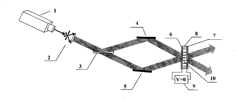
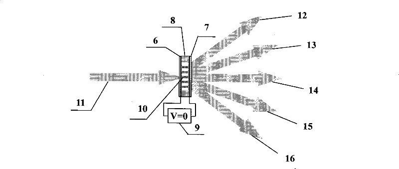
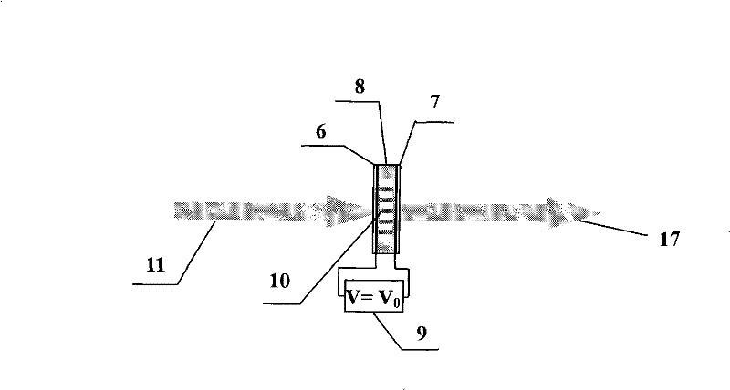
[0015] The raw material components of the polymer liquid crystal film are: the monomer is dimethylolpropane triacrylate monomer or trimethylolpropane triacrylate monomer, the crosslinking agent is N-vinylpyrrolidone, and the light The initiator is N-phenylglycine, the photosensitizer is sodium tetrachlorotetraiodofluorescein, the nematic liquid crystal is n-pentylcyanobiphenyl liquid crystal, and the mass ratio of the five components is: 35.4:13:1:0.6 : 50. The thickness of the polymer liquid crystal film prepared between two ITO glass substrates is 20-40 microns. Such as figure 1 , the laser light output by the laser 1 is expanded by the spatial light filter 2, divided into two beams by the beam splitter 3, and then reflected by the reflectors 4 and 5 so that the two beams of light are at a small angle (0.5 ~5 degrees) coupling to generate a Raman-Nath type grating 10, wherein the exposure time is 5-6 seconds. No voltage is applied to the ITO glass substrates 6 and 7 durin...

Embodiment 2

[0017] The operating steps are the same as in Example 1. The monomer is tetramethylolpropane triacrylate, the crosslinking agent is hexamethylolmelamine, the photoinitiator is azobenzene, etc., the photosensitizer is methyl red, and the nematic liquid crystal is nitrile diphenyl or In the terphenyl mixed liquid crystal, the mass ratio of the five components is: 40.3:10:1.5:0.7:47.5. The thickness of the polymer liquid crystal film is 40-60 microns. During exposure, the angle between the two laser beams is 5-10 degrees, and the exposure time is 6-8 seconds. The switch state is the same as in embodiment 1.


PUM

PropertyMeasurementUnit
thicknessaaaaaaaaaa
thicknessaaaaaaaaaa

Abstract

The invention relates to an electric control switch type holographic polymer dispersed liquid crystal diffractive beam splitter, which belongs to the optics technology field. In the invention, a mixture including monomer, photosensitizer, photoinitiator, crosslinking agent and liquid crystal in a certain proportioning is filled between two ITO glass substrates to prepare a polymer liquid crystal film; the polymer liquid crystal film is exposed by the interference light field coupled by two laser beams; the interference fringes with non-uniform light intensity distribution impels the photo polymerization generated inside the film and the phase separation to modulate refractive index periodically; the exposed polymer liquid crystal film generates Raman-Nath diffraction which can realizationoptics beam-splitting. The on / off state of the beam splitter can be controlled by low direct voltage. The optics beam splitter can split both the beam without information and the beam carrying information; and can work under different wavelengths. The invention can be used in the fields of optics interconnection, image processing, precise measuring optical computing, optical disk storage and photoelectric conversion.

Description

technical field [0001] The invention belongs to the field of optical technology, and in particular relates to an optical beam splitter. Background technique [0002] Beam splitter is one of the basic optical components, and has a wide range of applications in optical fields such as optical interconnection, image processing, precision measurement, optical computing, optical disk storage, and photoelectric conversion. Traditional optical beam splitters use a refraction-reflection system to split light through multiple refractions and reflections. This kind of beam splitting system has the disadvantages of complex structure, large volume, high energy loss, poor uniformity, and the coating in the system is easily damaged under high power, which cannot meet the requirements of miniaturization, integration and high efficiency of the optical system. [0003] The electronically controlled switchable holographic polymer dispersed liquid crystal diffraction beam splitter uses the Ram...

Claims


Application Information

Patent Timeline
Patent Type & Authority Patents(China)
IPC IPC(8): G02F1/1334G02F1/133
Inventor 高洪跃刘建华戴海涛尹德金浦海辉高斌
Owner FUDAN UNIV
Learn More