Optical analysis reading device
A reading device and optical analysis technology, which is applied in the direction of chemical reaction of materials for analysis, etc., can solve the problem of inability to compare test results, and achieve the effects of intuitive display results, low cost and simple operation.
- Summary
- Abstract
- Description
- Claims
- Application Information
AI Technical Summary
Problems solved by technology
Method used
Image
Examples
Embodiment 1
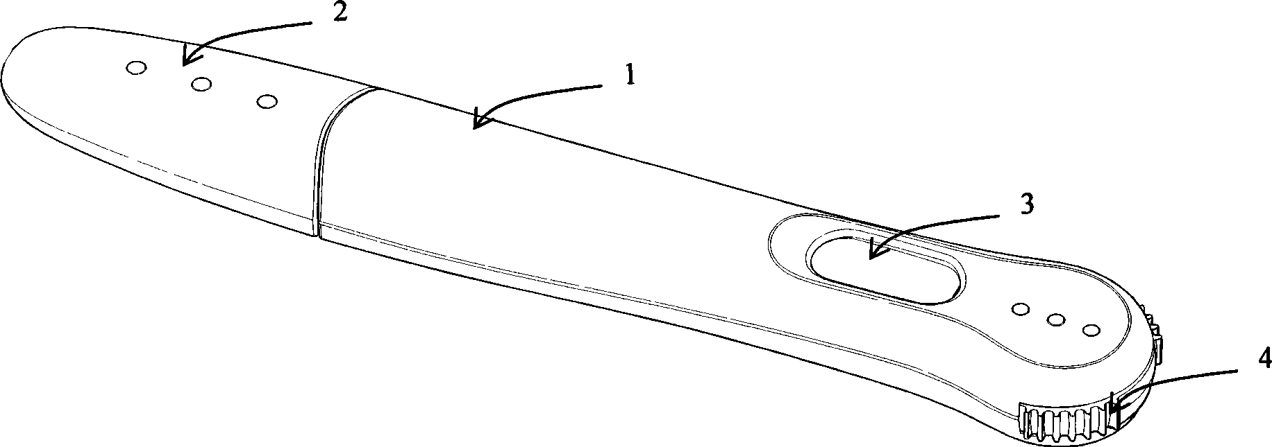
[0065] Such as figure 1 As shown, the shape of the optical analysis reading device is pen-shaped. In terms of appearance, the device includes a housing 1 made of opaque synthetic plastic, a cover 2, a liquid crystal display 3 and a battery 4. The liquid crystal display 3 can display the analysis result information in a qualitative or quantitative manner. When the test is started, the cover 2 is removed, the liquid sample comes into contact with the water-absorbing stick at the front end of the reading device, and the reading device is activated at the same time. When the liquid in the water-absorbent stick is transferred to the reagent strip 5 inside the housing 1, the reagent strip 5 can be used to detect the presence or absence of a sample. After the test is completed, the test result can be displayed on the liquid crystal display 3 to display the final result, and at the same time, the battery 4 can be peeled out of the reading device to avoid electric leakage.
[0066] The in...
Embodiment 2
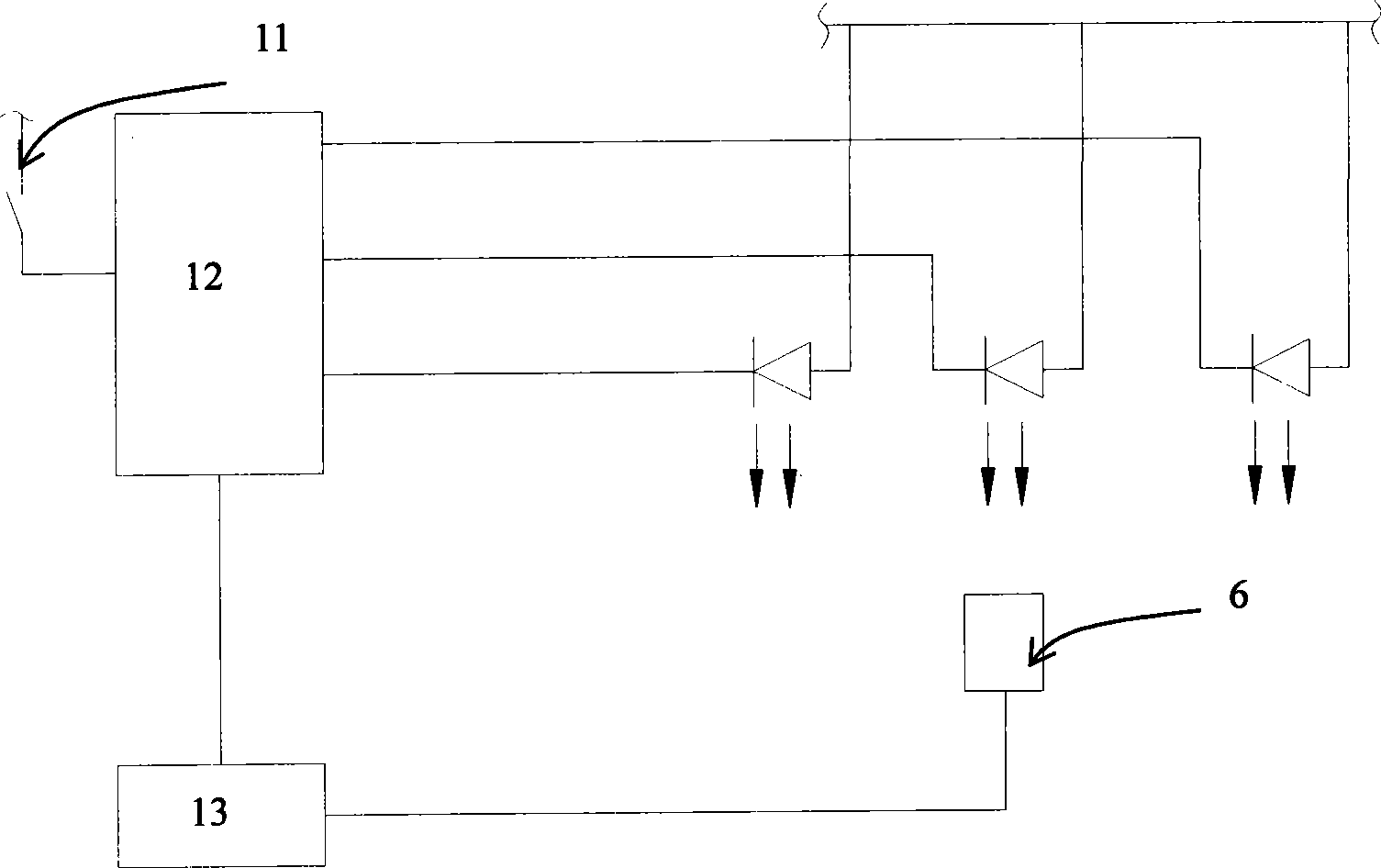
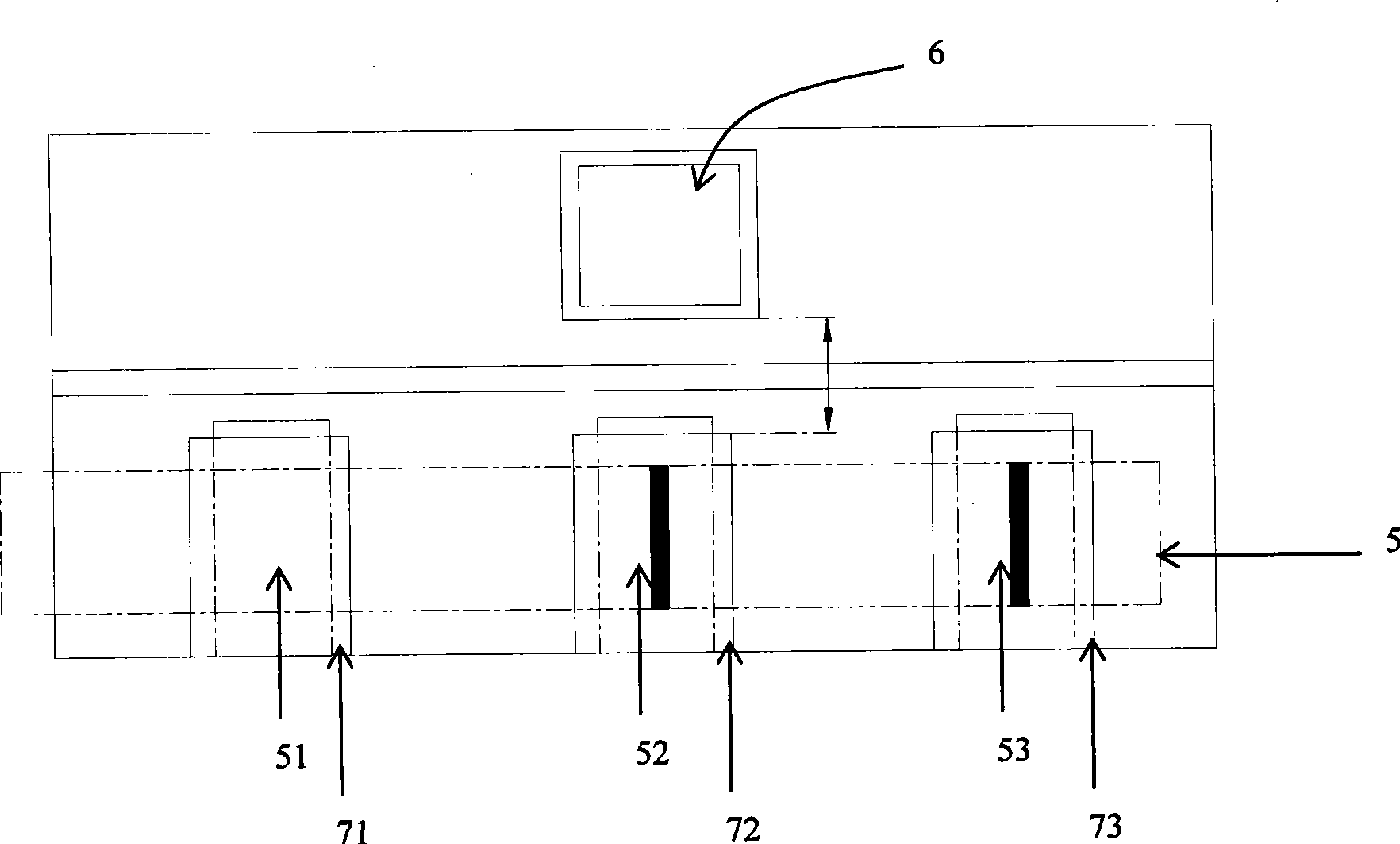
[0069] This embodiment describes the preferred configuration in Embodiment 1 in more detail. The light detector 6 is a photodiode (PD), and the light source 7 is a light emitting diode (LED). Such as image 3 with Figure 4 As shown, the reading device includes a PD and three LED lights. The light emitted from the first LED 71 illuminates the reference area 51 on the reagent strip 5, the light emitted from the second LED 72 illuminates the detection area 52 of the reagent strip 5, and the light emitted from the third LED 73 illuminates the reagent strip 5的控制区53。 The control area 53. The opaque fence 8 separates each LED light optically, ensuring that each LED light can only illuminate the corresponding area. Figure 5 The spatial relationship between the LED lamp and the PD is shown. There is a partition 9 between the LED lamp and the PD to prevent the light from the light source 7 from directly irradiating the PD. Any light incident on the reagent strip 5 at an angle β will be re...
Embodiment 3
[0071] In Embodiment 3, the effective area of the photodetector 6 is 1.5 mm×1.5 mm. The light source 7 provides light, and at least part of the light has a wavelength of 635 nm. The material used for the partition assembly 10 is black nylon.
PUM
 Abstract
Description
Claims
Application Information
 - Generate Ideas
- Intellectual Property
- Life Sciences
- Materials
- Tech Scout
- Unparalleled Data Quality
- Higher Quality Content
- 60% Fewer Hallucinations
Browse by: Latest US Patents, China's latest patents, Technical Efficacy Thesaurus, Application Domain, Technology Topic, Popular Technical Reports.
© 2025 PatSnap. All rights reserved.Legal|Privacy policy|Modern Slavery Act Transparency Statement|Sitemap|About US| Contact US: help@patsnap.com


