
Fast measuring device and measuring method of optical element

A technology for measuring devices and optical components, applied in the field of spectrum analyzers, can solve the problems of not being suitable for the measurement of samples with complex shapes, the inability to change the receiving optical path at will, and the high requirements for debugging and installation, so as to simplify the steps of mechanical transmission and optical adjustment, improve The level of reproducibility and instrument stability, the effect of reducing the requirements of the use environment

Inactive Publication Date: 2009-09-30
宋光均
View PDF0 Cites 5 Cited by
  • Summary
  • Abstract
  • Description
  • Claims
  • Application Information

AI Technical Summary

Problems solved by technology

Since the grating is rotated by a mechanical device in such a spectral analysis instrument, a certain scanning time is required to ensure the wavelength resolution, and the measurement speed is slow, and the optical index measurement of the measured optical materials and components cannot be obtained immediately, and the detection efficiency for large quantities of products is low.
Due to the use of precision mechanical rotating devices, the existing measuring instruments have high requirements for debugging and installation, resulting in high instrument cost
At the same time, the overall optical path design of existing measuring instruments lacks flexibility, and the receiving optical path cannot be changed at will. The measured values ​​at different points can only be changed by adjusting the sample placement, which is not suitable for the measurement of samples with complex shapes.

Method used


Image

  • Fast measuring device and measuring method of optical element
  • Fast measuring device and measuring method of optical element

Examples


Embodiment Construction

[0009] The present invention will be further described below by means of drawings and specific embodiments.

[0010] The following descriptions are only preferred embodiments of the present invention, and therefore do not limit the protection scope of the present invention.

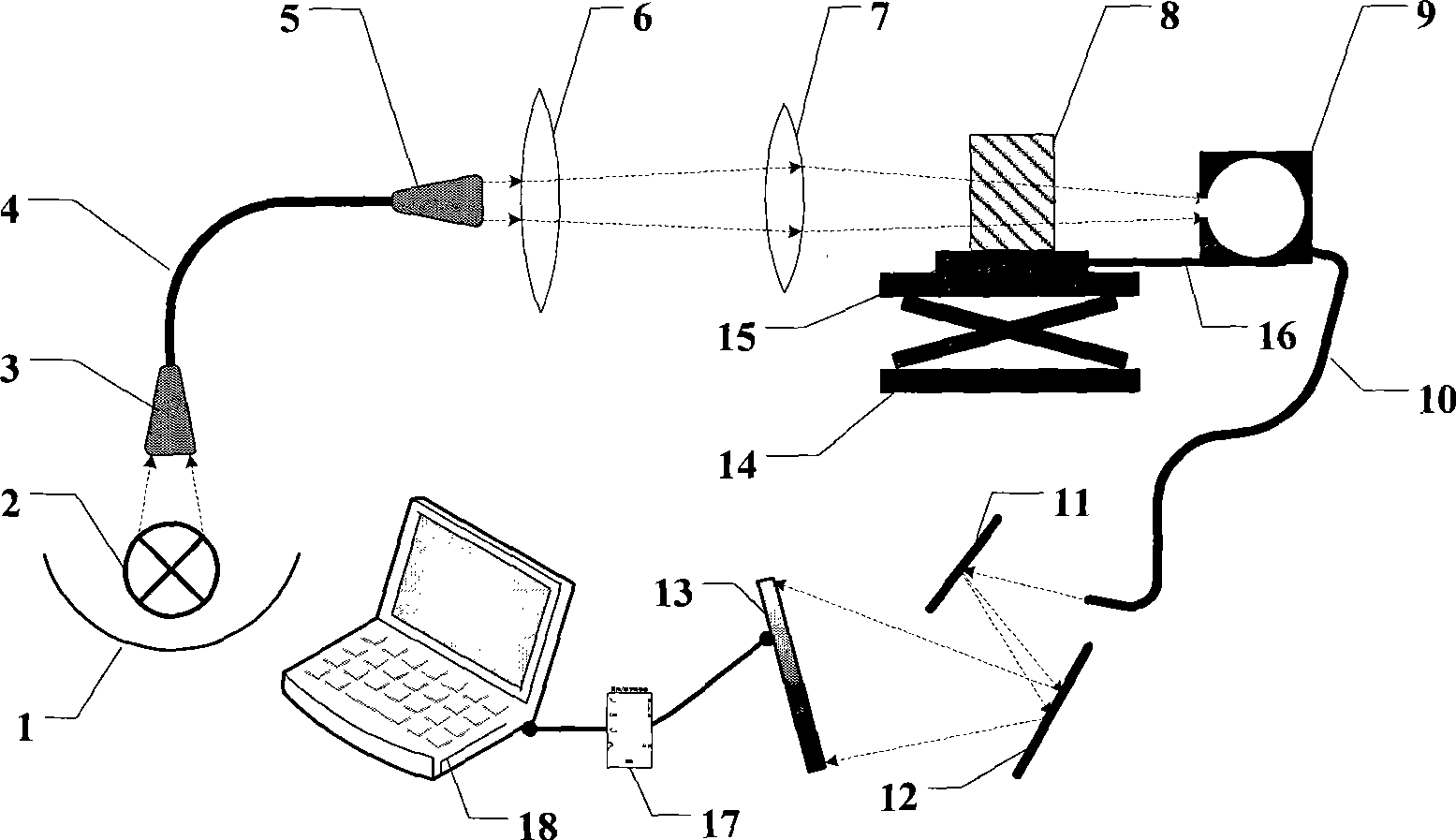
[0011] Such as figure 2 As shown, the present invention is mainly composed of a light source system, a light guide system, a sample placement mechanism, a lighting system, a rear spectroscopic system, an array photoelectric conversion system, and a data analysis system. The present invention can select different types of lamps such as tungsten-halogen lamps or deuterium lamps as the light source (2) according to the wavelength, and the light is converged to the optical fiber light guide lens (3) after being concentrated and reflected by the reflector (1), and then transmitted by the optical fiber (4) To the fiber exit lens (5), through the lenses (6), (7) adjusted to approximately parallel beams to irra...


PUM


Abstract

The invention discloses a fast measuring device and a measuring method of an optical element. The measuring device comprises a light source system, a light guiding system, a sample placing mechanism, a lighting system, a rear-mounted optical splitting system, an array type photoelectric transformation system and a data analyzing system. The measuring device is a fast, flexible and accurate measuring instrument which is invented aiming at the complex requirement of research and development of optical parts and monitoring of quality of products. The measuring device is characterized by adopting a rear-mounted optical splitting mode and combining a semifixed and adjustable sample platform and a movable lighting system, being capable of measuring optical parameters of transmission, reflection and dispersion for regular or irregular optical elements and adopting an array type photoelectric transformation element to finish signal collection and conversion. The measuring device has the characteristics of fast measuring speed, suitability of samples with complex shapes, good measuring reproduction quality, flexible collocation and low price, thereby being suitable for optical parameter measurement and quality monitoring of various optical elements.

Description

Technical field: [0001] The invention relates to a spectrophotometer, in particular to a spectrum analyzer for measuring reflection, transmission, refraction and scattering optical indexes of various optical materials and components. Background technique: [0002] With the development of optoelectronic technology, more and more optical components have been applied to the national economy and daily life, ranging from aerospace to mobile TV. Accurate and fast photometric measurement is required in the process of product development, optical material selection and component design, product production, process condition determination and product quality verification. In view of the quality monitoring requirements of optical components, the commonly used instruments currently used for the measurement of various optical indicators such as reflection, transmission, and scattering of various optical materials and components are pre-spectroscopy. Existing spectrum analysis instrumen...

Claims


Application Information

Patent Timeline
IPC IPC(8): G01M11/02
Inventor 蹇华丽宋光均姚建政郑祥利
Owner 宋光均
Learn More