Lens driving device

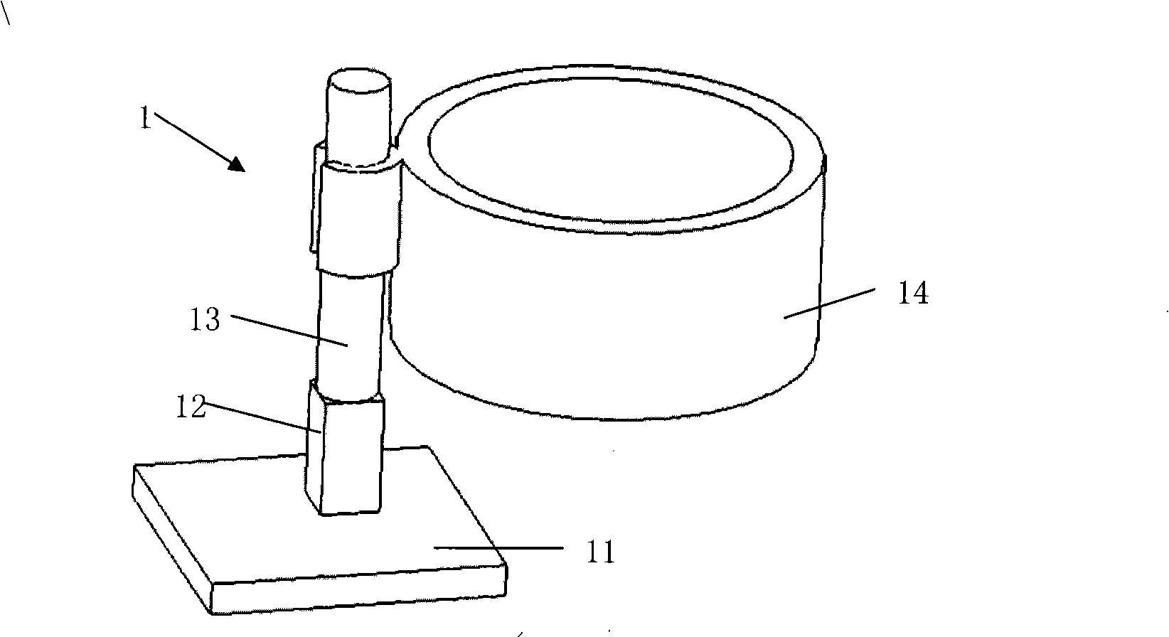
A lens driving device and lens technology, applied in the field of photography, can solve the problems of the driving rod 13 falling off, the poor response ability of the piezoelectric motor 12, and the poor response ability of the piezoelectric motor 12 vibration, etc., and achieve good bonding effect

Inactive Publication Date: 2009-09-23
JOHNSON ELECTRIC SHENZHEN
View PDF0 Cites 11 Cited by
  • Summary
  • Abstract
  • Description
  • Claims
  • Application Information

AI Technical Summary

Problems solved by technology

[0005] Although this scheme is simple in structure and easy to assemble, it still has the following disadvantages: 1. In order to ensure the stroke, the driving rod 13 needs to have a certain length, but the farther the distance between the lens holder 14 and the piezoelectric motor 12, the greater the impact on the piezoelectric motor 12. The poorer the response ability of the motor 12 vibration; 2, this structure is easily affected by the quality of the lens holder 14, the greater the quality of the lens holder 14, the poorer its response ability to the vibration of the piezoelectric motor 12; 3, the driving rod 13 and the pressure The adhesion between the electric motors 12 is affected by the length of the rod, the cross-sectional area of ​​the rod and the quality of the rod. The bonding area between the driving rod 13 and the piezoelectric motor 12 is relatively small compared to the size of the driving rod 13, and the driving rod 13 is easy to detached from piezo motor 12

Method used


Image

  • Lens driving device
  • Lens driving device
  • Lens driving device

Examples


Embodiment Construction

[0015] In order to make the technical problems, technical solutions and beneficial effects to be solved by the present invention clearer, the present invention will be further described in detail below in conjunction with the accompanying drawings and embodiments. It should be understood that the specific embodiments described here are only used to explain the present invention, not to limit the present invention.

[0016] Such as image 3 and Figure 4 As shown, the lens driving device according to one embodiment of the present invention includes a base 20, a guide post 25 fixed on the base 20, a lens holder 30 slidably installed on the guide post 25, and a motor installed on the lens holder. A seat 40 , a piezoelectric motor 50 fixed at one end to the motor seat, a friction coupling head 60 fixed at the other end of the motor, and a preload assembly 70 .

[0017] The lens holder 30 has a through hole 32 and a receiving cavity 34 . A bead holder 36 is fixed in the through ...


PUM


Abstract

The invention provides a lens driving device, which comprises a base, a guide pillar fixed on the base, a lens bracket arranged on the guide pillar in a sliding mode, a motor seat arranged on the lens bracket, a piezoelectric motor, a friction coupling head, and a pre-tightening assembly arranged between the motor seat and the lens bracket, wherein one end of the piezoelectric motor along the optical axis direction of a lens is fixedly connected with the motor seat, while the other end is fixedly connected with the friction coupling head; and the pre-tightening assembly resists against the motor seat, and generates a first resisting component vertical to the optical axis direction of the lens to keep the sliding contact of the friction coupling head and the guide pillar and a second resisting component in parallel with the optical axis direction of the lens to keep the sliding contact of one end of the motor seat and the lens bracket. When the piezoelectric motor is connected with a driving signal which can slowly extend and quickly shrink, or slowly shrink and quickly extend the piezoelectric motor, the piezoelectric motor drives the lens bracket through the motor seat to move forwards or backwards along the optical axis direction of the lens. In the lens driving device, one end of the piezoelectric motor drives the lens bracket through the motor seat, thus the stroke and the quality of the lens bracket cannot influence the response capacity of the lens bracket on the vibrations of the piezoelectric motor.

Description

【Technical field】 [0001] The invention relates to the technical field of imaging, in particular to a lens driving device. 【Background technique】 [0002] With the popularization of mobile phones and the diversification of their functions, mobile phones with auto-focus cameras will have increasingly broad market prospects. The existing auto-focus mobile phones on the market usually use electromagnetic induction motors, which have the advantages of high speed and high efficiency, but the disadvantages are that the positioning accuracy is not high, it cannot be quickly self-locked, it is difficult to miniaturize, etc., and it is not suitable for current mobile phones. The popular trend of cameras getting smaller and smaller. [0003] Piezoelectric motors have the advantages of high positioning accuracy, low speed and high torque, simple structure, and no electromagnetic interference. They are now widely used in autofocus mobile phone camera modules. The two main driving metho...

Claims


Application Information

Patent Timeline
Patent Type & Authority Applications(China)
IPC IPC(8): G02B7/09H02N2/00
Inventor 石斌李红李兴全张勇刚
Owner JOHNSON ELECTRIC SHENZHEN
Why Eureka
Try Eureka