Metallic heat exchanger tube

A heat exchange tube, metal technology, applied in heat exchange equipment, tubular elements, heat transfer modification and other directions, can solve the problem of not being able to fully increase bubbles

Active Publication Date: 2009-09-16
WIELAND WERKE AG
View PDF15 Cites 8 Cited by
  • Summary
  • Abstract
  • Description
  • Claims
  • Application Information

AI Technical Summary

Problems solved by technology

What these inventions have in common is that the structure on the bottom of the tank has no concave structure, therefore, the generation of air bubbles cannot be sufficiently improved

Method used


Image

  • Metallic heat exchanger tube
  • Metallic heat exchanger tube
  • Metallic heat exchanger tube

Examples


Embodiment Construction

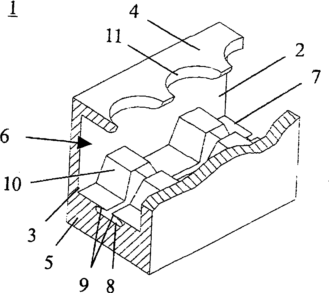
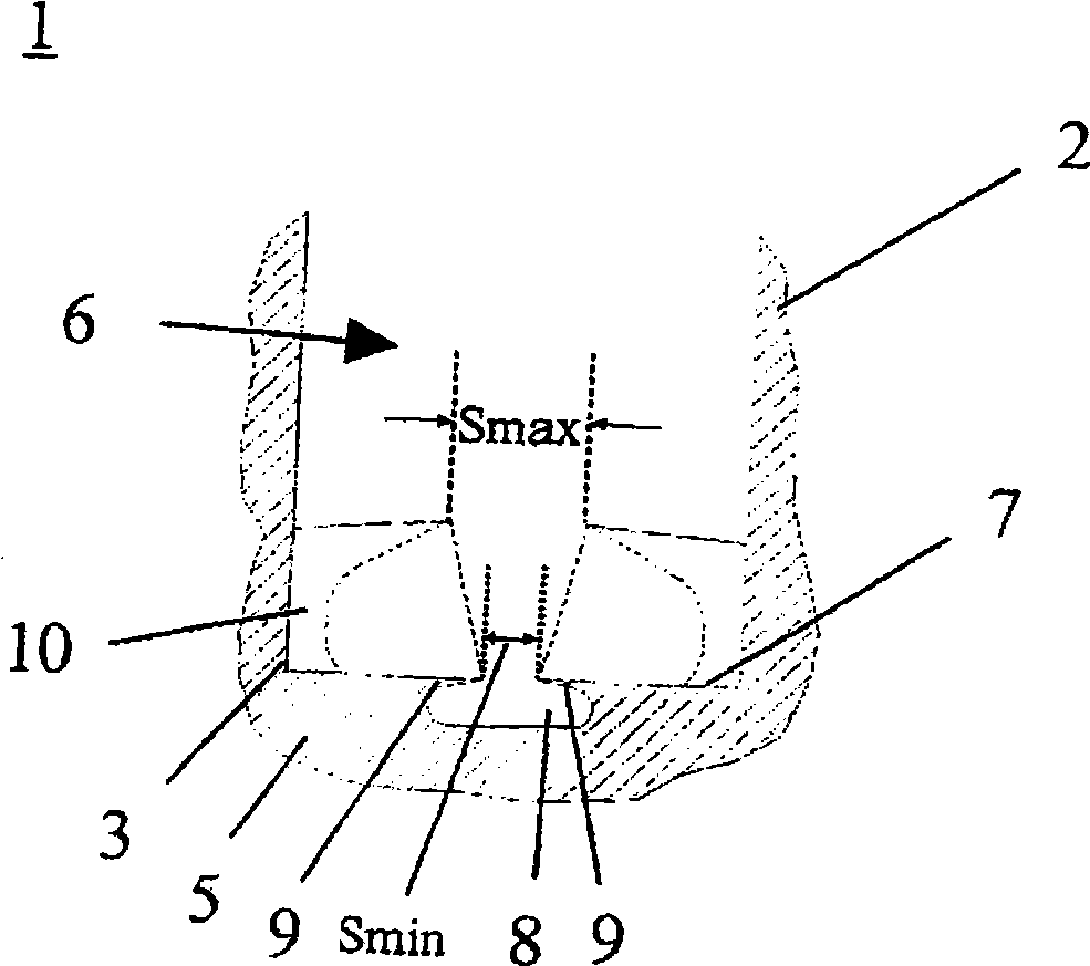
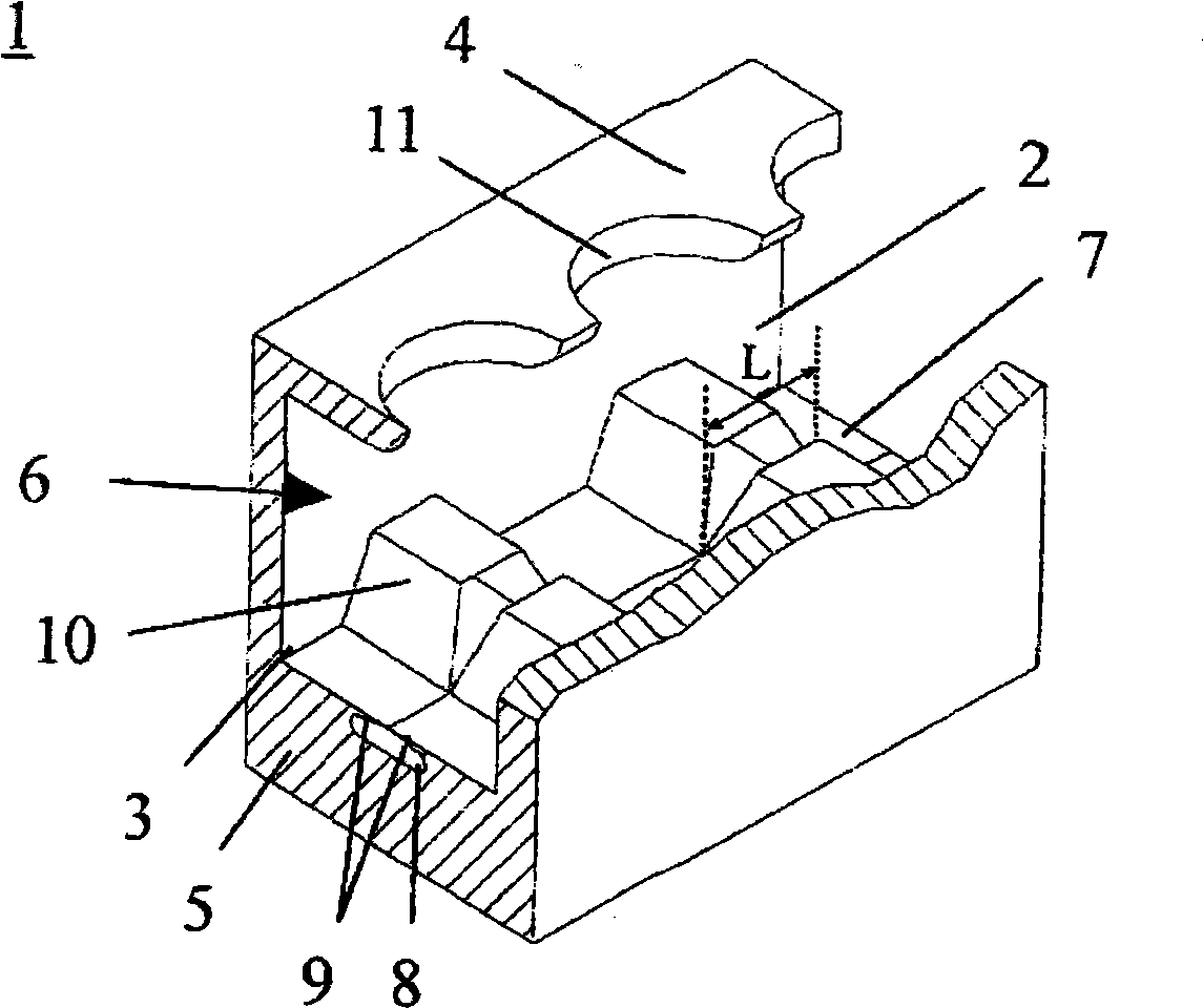
[0042] figure 1A view of the outside of a length of pipe of the present invention is shown. The integrally rolled ribbed tube 1 has ribs 2 running helically on the outside of the tube, between which initial grooves 6 are formed. The struts 2 extend continuously outside the tube along the delay line without interruption. The rib base 3 protrudes substantially radially from the tube wall 5 . The proposed rib tube 1 forms a recessed secondary groove 8 in the region of the groove bottom 7 where the primary groove 6 extends between two adjacent ribs 2 . The secondary groove 8 is delimited with respect to the primary groove 6 by a pair of mutually opposite material protrusions 9 formed of the material of the adjacent bead base 3 . The material protrusions 9 extend continuously along the initial groove 6, wherein a space S is formed between opposing material protrusions 9, which changes at a prescribed interval. When changing the cross-section of the secondary groove 8, the shape...


PUM

PropertyMeasurementUnit
Lengthaaaaaaaaaa

Abstract

The invention relates to a metallic heat exchanger tube with fins which run helically around the outside of the tube, are molded integrally therefrom and are of continuous design and the fin base of which protrudes substantially radially from the tube wall, and with primary grooves located between respectively adjacent fins. At least one undercut secondary groove is arranged in the region of the groove base of the primary grooves. Said secondary groove is delimited toward the primary groove by a pair of mutually opposite material projections formed from material of respectively adjacent fin bases. Said material projections extend continuously along the primary groove. The cross section of the secondary groove is varied at regular intervals without having an influence on the shape of the fins. There is a spacing between the opposite material projections, said spacing being varied at regular intervals, as a result of which local cavities are formed.

Description

technical field [0001] The invention relates to a metal heat exchange tube according to the preamble of claim 1 , having a one-piece and continuously formed brace that runs helically on the outside of the tube. [0002] Metal heat exchange tubes of this type are especially used for vaporizing highly pure substances or liquids in mixtures on the outside of the tubes. Background technique [0003] Evaporation occurs in many areas of cooling and air conditioning technology as well as in process energy technology. Tube bundle heat exchangers are usually used to vaporize high-purity substances or liquids in mixtures on the outside of the tubes and cool brine or water on the outside of the tubes. This device is called a flood vaporizer. [0004] By increasing the heat transfer outside the tubes and inside the tubes, the size of the vaporizer is significantly reduced. As a result, the manufacturing costs of such devices are reduced. In addition, to reduce the filling amount of ...

Claims


Application Information

Patent Timeline
IPC IPC(8): F28F1/36
CPCF28F1/36F28F13/187F28F1/40F28F1/10F28F1/42
Inventor 安德烈亚斯·比特勒吉恩·埃尔·海约尔安德烈亚斯·诺普菲勒罗那尔德·卢茨安德烈亚斯·舒维特拉
Owner WIELAND WERKE AG
Why Eureka
Try Eureka