Drilling manufacturing process of induction magnet ring plate

A production process and induction magnetic ring technology, applied in the direction of printed circuit manufacturing, electrical components, printed circuits, etc., can solve the problems of easy wire drawing, high cost, waste of resources, etc., achieve fiber cutting and chip removal improvement, and strong reliability. , the effect of reducing costs

Inactive Publication Date: 2013-06-05
SHENZHEN TONGXIN CIRCUIT ELECTRONICS
View PDF2 Cites 0 Cited by
  • Summary
  • Abstract
  • Description
  • Claims
  • Application Information

AI Technical Summary

Problems solved by technology

[0011] However, the hole diameter of this kind of continuous drilling method cannot be controlled within 10um, which directly affects the electrical performance of the product. The main reason is that continuous drilling has a large impact on the hole wall, which is prone to wire drawing, and the heat of the drill tip cannot be effectively removed. The wick effect cannot be controlled, resulting in a waste of resources and high costs

Method used


Image

  • Drilling manufacturing process of induction magnet ring plate
  • Drilling manufacturing process of induction magnet ring plate
  • Drilling manufacturing process of induction magnet ring plate

Examples


Embodiment Construction

[0029] The present invention is described in further detail below with preferred embodiment:

[0030] The thin plate aperture (0.25mm) hole and hole spacing of the present invention is 0.25mm (per m 2 The holes are more than 1,000,000) to produce boards, and the hole thickness and wicking effect are changed. The original hole thickness is controlled below 30um, and the wicking effect is controlled within 1mil. After the design, the hole thickness control is below 10um, and the wicking effect is controlled within 0.05mil. To meet the above requirements, the material and parameters need to be modified.

[0031] For the design change of the inner core board, complete the layout design of the PCB inner layer through the existing circuit board auxiliary software, modify the line width and hole spacing, select and delete the independent PAD to ensure uniform glue flow during lamination, and A square flow blocking block is designed on the inner process side, and at the same time, it...


PUM


Abstract

The invention discloses a drilling manufacturing process of an induction magnet ring plate. A continuous drilling method is adopted in a common multi-layer plate hole drilling manufacturing process applied to a computer and network equipment at present; the electric property of a product is affected by hole roughness; the continuous drilling generates larger impact force on a hole wall; wire drawing is easy to generate; and the drill bit heat can not be effectively released. In the drilling manufacturing process provided by the invention, hole location, hole number, hole diameter, hole shape,inter-line spacing and layout design can be finished by utilizing line plate auxiliary software genesis; the drilling manufacturing process comprises location hole drilling, laminating, primary hole drilling, secondary hole drilling, hole blowing and checking; continuous-hole drilling is changed into separated-hole drilling; two same cutters are utilized for production; the inter-hole spacing is maintained at 0.75mm; the drilling rotation speed mainly targets the continuous design parameter which is more than or equal to 0.25mm; the rotation speed is high and the cutting rate is low; and wiredrawing cannot be generated easily in the production process, thus overcoming hole roughness and wick effect caused by hole burning and fiber break in drilling process since the inter-line spacing issmall; and all performance test requirements can be met.

Description

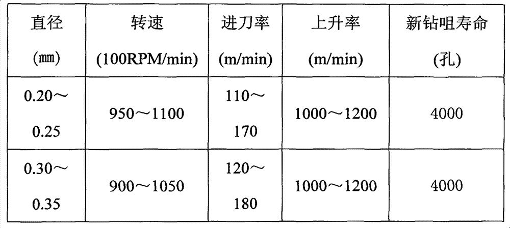
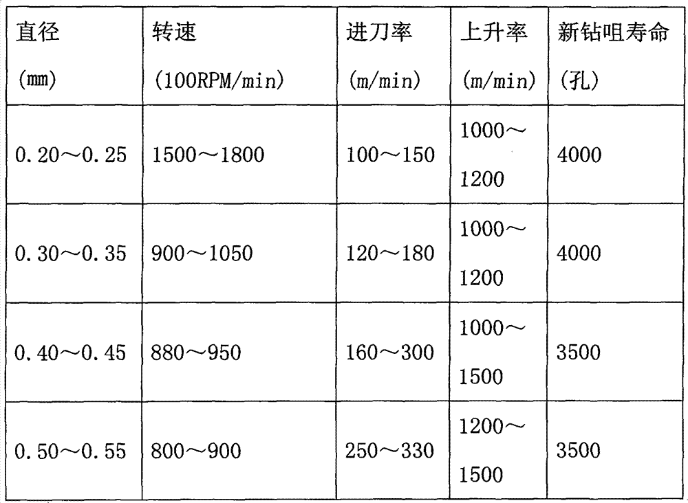
technical field [0001] The invention relates to the field of electronic technology manufacturing, in particular to a drilling process for an induction magnetic ring plate. Background technique [0002] The common multi-layer board drilling process used in the existing computer and network equipment is as follows: [0003] A. Use the existing circuit board auxiliary design software genesis to complete the basic PCB layout design, mainly the inner core circuit graphic design, press-fit structure, hole position, hole number, aperture and hole-shaped conduction circuit design layout to meet customers Assembly requirements. [0004] B. Drill positioning holes → stack plates → drill holes → check → transfer to the next process. [0005] The stacking method before drilling is: aluminum sheet + A1 copper plate to be drilled + A2 copper plate to be drilled + backing plate. [0006] C. Ordinary multi-layer board drilling production parameters: [0007] D. The production parameters...

Claims


Application Information

Patent Timeline
Patent Type & Authority Patents(China)
IPC IPC(8): H05K3/00B23B35/00
Inventor 阙民辉张柏勇
Owner SHENZHEN TONGXIN CIRCUIT ELECTRONICS
Why Eureka
Try Eureka