Parallel type thermal differential evaporation cold (hot) water machine

An evaporative cooling and parallel technology, which is applied in the direction of evaporator/condenser, refrigerator, compressor with multiple evaporators, etc. Ice and other problems, to achieve the effect of improving energy efficiency ratio, facilitating maintenance, and increasing the average evaporating temperature

Inactive Publication Date: 2009-09-16
福州市仓山区宇泓空调节能技术有限公司
View PDF0 Cites 6 Cited by
  • Summary
  • Abstract
  • Description
  • Claims
  • Application Information

AI Technical Summary

Problems solved by technology

[0003] The disadvantages of this cold (hot) water unit are: (1) Although the water temperature gradually drops (rises) when the cold (hot) water flows through the evaporator, since the refrigeration system has only one evaporator, the evaporation pressure It can only be determined by the water temperature at the outlet of the evaporator with the lowest temperature (highest), and the relatively high temperature at the front end of the cold water cooling process cannot be used in the refrigeration cycle. According to the principle of refrigeration, the lower the evaporation temperature (pressure), the lower the refrigeration efficiency; The equivalent Carnot cycle diagram of the relationship between efficiency and evaporation temperature is shown in Figure 5 (2) Since the efficiency of the single evaporator cold (hot) water unit decreases rapidly when the evaporation pressure drops, the utilization of low-temperature cold water and large temperature difference (large temperature difference between the inlet and outlet of the unit’s cold water) is limited.
Increasing the temperature difference between supply and return water has a great potential to improve the energy utilization efficiency of the air conditioning system, and reducing the cold water temperature and outlet temperature has a great impact on the dehumidification performance of the air conditioning system, and the improvement of dehumidification efficiency can also significantly improve the air conditioning system in the process of air treatment. Energy utilization efficiency; (3) During the refrigeration process, the temperature difference between the inlet and outlet of the cold water of a single evaporator is large, and when the outlet water temperature is near the freezing point, local overcooling and freezing may easily occur in the evaporator due to heat exchange dead angles, which will damage the unit

Method used


Image

  • Parallel type thermal differential evaporation cold (hot) water machine
  • Parallel type thermal differential evaporation cold (hot) water machine
  • Parallel type thermal differential evaporation cold (hot) water machine

Examples


Embodiment Construction

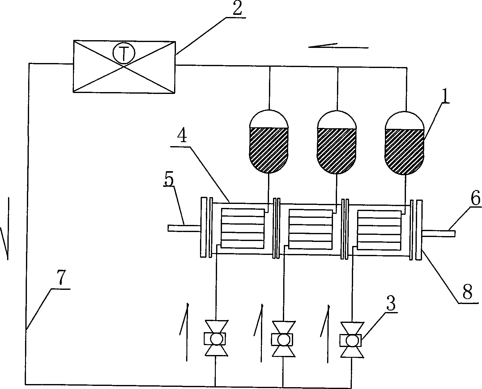
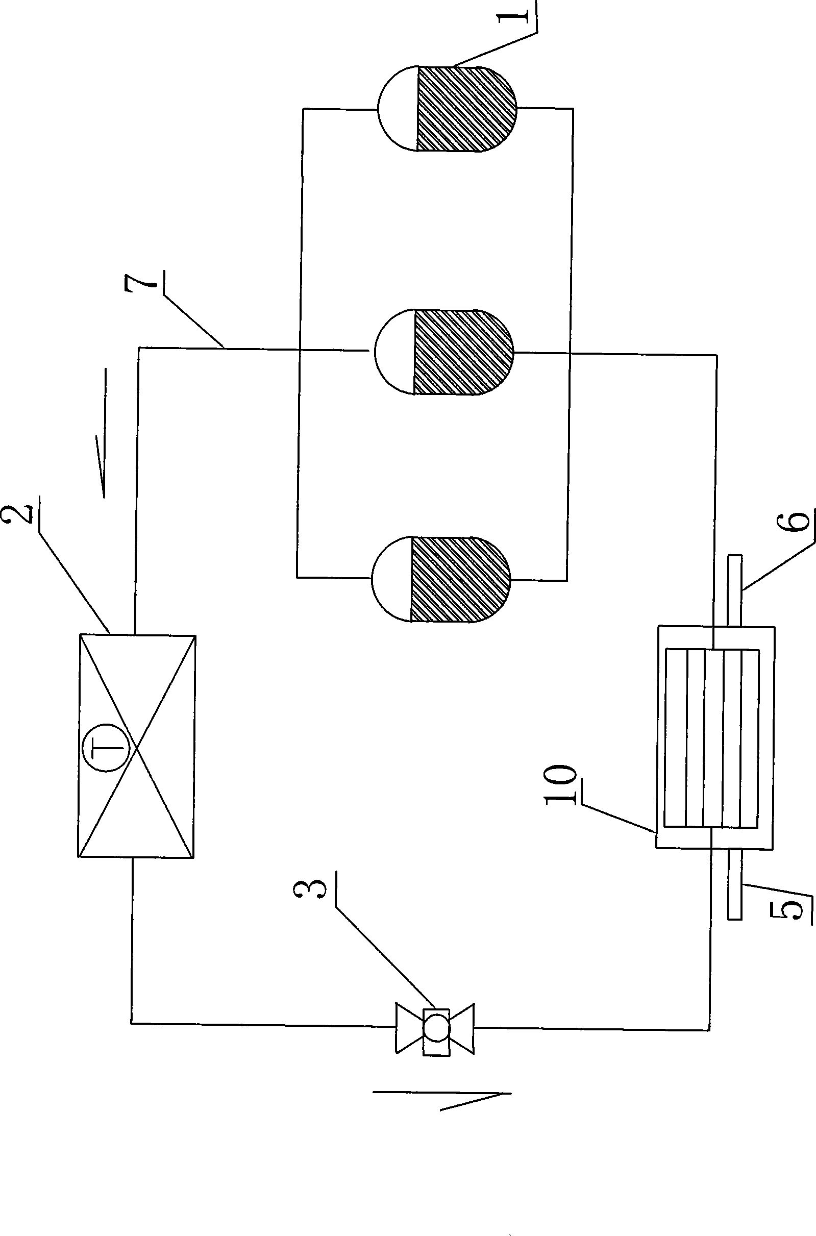
[0013] Such as figure 1 As shown, the present invention includes a condenser 2, two or more than two compressors 1, an evaporator cold water inlet pipe 5, an evaporator cold water outlet pipe 6, a refrigerant pipe 7, an evaporation unit 8 having the same number as the compressor, and The number of throttle valves 3 is the same as that of the compressors. A compressor, an evaporation unit and a throttle valve are sequentially connected to form a unit. Multiple units are arranged in parallel and then connected in series with a condenser to form a circulation system.

[0014] A plurality of evaporating units are connected in series along the water flow direction to form an evaporator, and the cold water outlet of the previous evaporating unit is connected to the cold water inlet of the following evaporating unit, so that the evaporators 8 are connected in series to form a series combination. The evaporator cold water inlet pipe 5 is connected from one side of the evaporator, and...


PUM


Abstract

The invention relates to a parallel type thermal differential evaporation cold(hot) water machine, comprising a condenser, two or more than two compressors, an evaporator cold-water inlet pipe, an evaporator cold-water outlet pipe, a refrigerant pipe, evaporation units of the same number with compressors and throttle valves of the same number with compressors, wherein the throttle valves, the evaporator units, compressors are connected together in turn and with one condenser to form a circulation system; the evaporator units are connected together side by side along flow direction to form one evaporator, the cold-water outlet pipe of the former evaporator unit is connected with the cold-water inlet pipe of the post evaporator unit, thus a parallel evaporator is formed. The parallel type thermal differential evaporation cold (hot) water machine has features of energy saving, consume reduction, convenient maintenance.

Description

Technical field: [0001] The invention relates to a parallel type differential temperature evaporative cold (hot) water unit. Background technique: [0002] Due to the limitation of early design concepts, the existing multi-machine compression cold (hot) water units for air conditioners are all designed as single-evaporator single-pressure evaporation systems to simplify their structure and reduce costs. Its system schematic diagram is as follows image 3 As shown, its working process is mainly as follows (auxiliary components are omitted for the convenience of description and the refrigeration process is taken as an example): the refrigerant evaporates into steam in the evaporator, absorbs the latent heat of vaporization (generated cooling capacity) during evaporation, and transfers the heat to the outside of the coil. The lowering of the cold water temperature produces low-temperature cold water. In order to make the evaporation process (refrigeration process) in the evapo...

Claims


Application Information

Patent Timeline
Patent Type & Authority Applications(China)
IPC IPC(8): F25B5/02F25B39/02F25B29/00
Inventor 李曹县吴金毅施孝增鄢庆春
Owner 福州市仓山区宇泓空调节能技术有限公司
Why Eureka
Try Eureka