


Quick Research
Generate reliable direction feasibility study reports for your R&D in just a few steps.

Technical Q&A
Discover and master advanced knowledge NOW. Basics, ideas, possibilities, all at once.

Find Solutions
As an expert in R&D theories, this can generate solutions to your technical problems instantly.

Evaluate Feasibility
Analyze your overall solution with one click, know your potential R&D risks in advance.

Monitor Landscape
Get weekly tech updates, stay abreast of the latest tech innovations and key insights.
Cast-in-place hollow lightweight inner partition wall
A technology for internal partition walls and hollow cores, which is applied in the on-site preparation of walls and building components, formwork/formwork/working frames, etc. It can solve the problems that the production scale is too small to meet the use of large buildings, and achieve improved sound insulation performance effect
- Summary
- Abstract
- Description
- Claims
- Application Information
AI Technical Summary
Problems solved by technology
Method used
Image

Examples
Embodiment 1
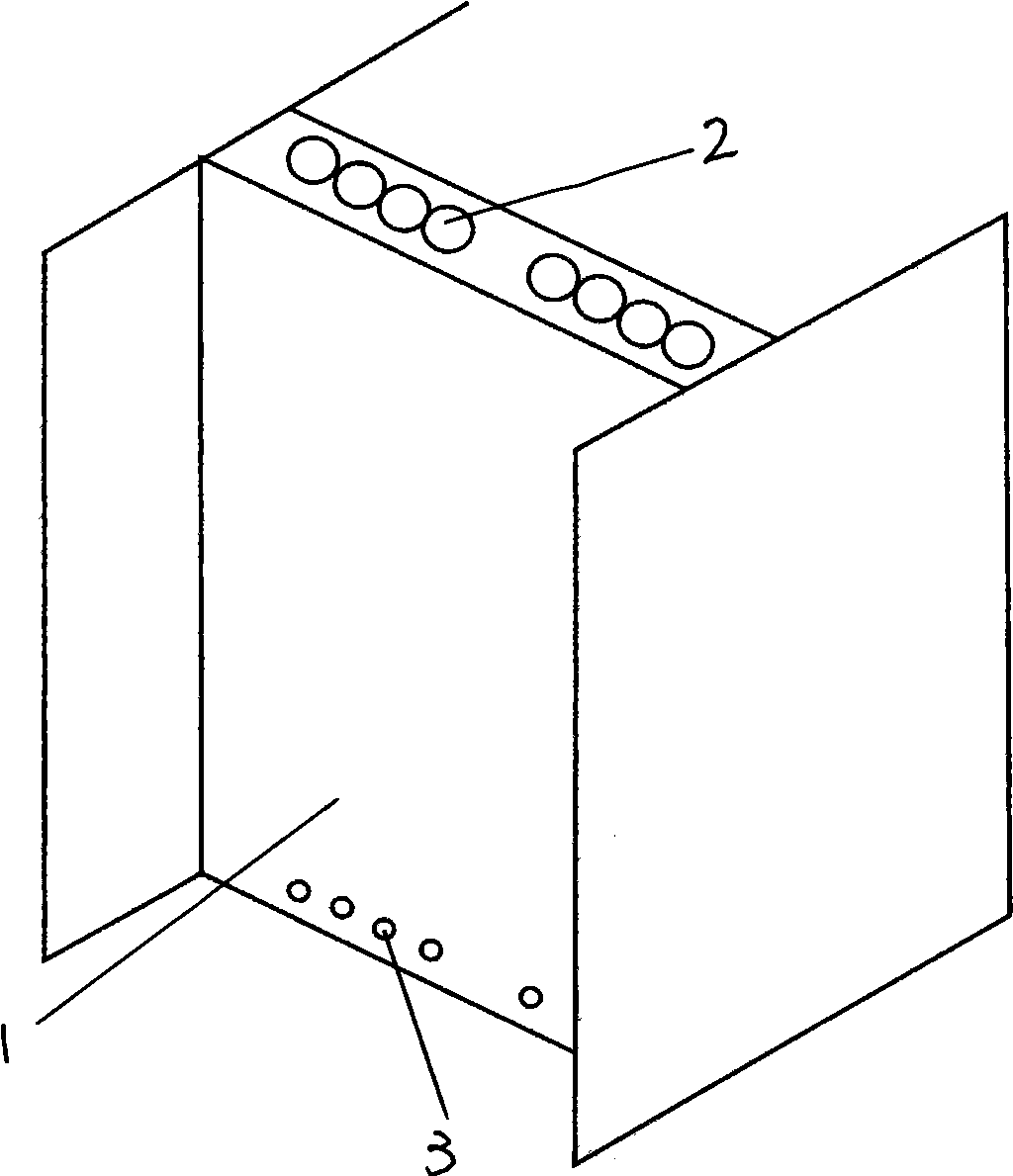
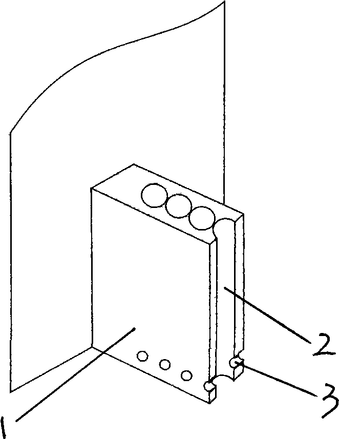
[0030] The cast-in-place hollow lightweight inner partition wall of this example is an L-shaped partition wall. In the wall body 1 made by the cast-in-place method, a hollow cylinder body 2 is inlaid, and the hollow cylinder body 2 is a hollow paper tube. Such as Figure three As shown, before the wall body is dry, the lower part of the hollow cylinder body 2 is provided with a ventilating and dehumidifying hole 3 , and the ventilating and dehumidifying hole 3 passes through the wall body 1 . The wall body 1 is a cement-based wall body. Such as Figure ten As shown in 2, the cast-in-place method is to fix a row of templates 8 on one side of the partition wall to be poured, then fix the hollow cylinder 2 in the middle of the partition wall to be poured, and the both sides of the hollow cylinder 2 are provided with Wall thickness control parts 4 (such as Figure four shown), and then fix a row of templates 8 on the other side of the partition wall to be poured, and the termi...
Embodiment 2
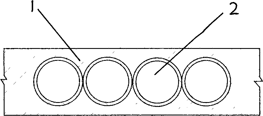
[0033] The cast-in-place hollow lightweight inner partition wall in this example, such as Figure 1 and Figure II As shown, it is a straight partition wall. Except that the wall body 1 is a gypsum-based wall body, the terminal of the formwork is connected to the existing wall body, and the self-leveling inorganic gelling slurry is a self-leveling gypsum-based slurry, the rest is the same as the first embodiment.
[0034] Among them, the self-leveling gypsum-based slurry is: 100% gypsum, mixed with appropriate amount of water.
Embodiment 3
[0036] The cast-in-place hollow lightweight inner partition wall in this example, such as Figure 1 and Figure II As shown, it is a straight partition wall. Except for the self-leveling gypsum-based slurry, the others are the same as in the second embodiment.
[0037] Among them, the self-leveling gypsum-based slurry is: gypsum 50-85%, limestone 5-35%, medium sand 5-40%, perlite 1-5%, starch ether 0.1-0.2%, defoamer 0.01-0.03 %, add appropriate amount of water and stir.
PUM
 Abstract
Description
Claims
Application Information
 - R&D Engineer
- R&D Manager
- IP Professional
- Industry Leading Data Capabilities
- Powerful AI technology
- Patent DNA Extraction
Browse by: Latest US Patents, China's latest patents, Technical Efficacy Thesaurus, Application Domain, Technology Topic, Popular Technical Reports.
© 2024 PatSnap. All rights reserved.Legal|Privacy policy|Modern Slavery Act Transparency Statement|Sitemap|About US| Contact US: help@patsnap.com