Method and device for low pressure treatment of coal coking gas
A technology for coking gas and coal, which is applied in chemical instruments and methods, separation methods, and dispersed particle separation, etc., can solve the problems of low pressure and large energy consumption, and achieve the effect of reducing energy consumption and increasing economic benefits.
- Summary
- Abstract
- Description
- Claims
- Application Information
AI Technical Summary
Problems solved by technology
Method used
Image
Examples
Embodiment 1
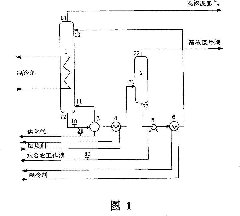
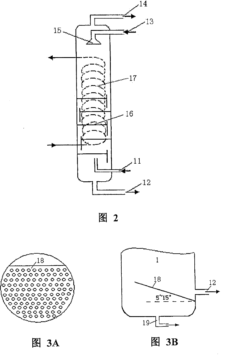
[0042] use figure 1 The technological process shown (wherein hydration reactor 1 adopts figure 2 The structure shown, no filter plate is set), and the simulated coking gas is separated to obtain high-concentration hydrogen and methane respectively. Wherein, the composition of the feed gas (equivalent to coking gas) entering the hydration reactor 1 is: H 2 (50.21mol%)+CH 4(49.79mol%); the operating temperature of the hydration reactor 1 is 3.0°C, and the operating pressure is 0.20MPa; the hydrate working fluid is an emulsion obtained by mixing the oil phase solution and the water phase solution according to the volume ratio of 4:1, and the oil phase solution is Commercially available No. 20 diesel oil, the aqueous phase solution is an aqueous solution containing tetrahydrofuran (wherein the molar fraction of THF is 0.06), and the aqueous phase solution contains Span-60 with a molar fraction of 0.0128, and contains 500ppm of dodecyl Sodium benzenesulfonate; the volume ratio ...
Embodiment 2
[0044] use figure 1 The technological process shown (wherein hydration reactor 1 adopts figure 2 The structure shown, no filter plate is set), and the simulated coking gas is separated to obtain high-concentration hydrogen and methane respectively. Wherein, the composition of the feed gas (equivalent to coking gas) entering the hydration reactor 1 is: H 2 (59.16mol%)+CH 4 (40.84mol%); the operating temperature of the hydration reactor 1 is 3.5°C, and the operating pressure is 0.96MPa; the hydrate working fluid is the oil phase solution and the water phase solution in a volume ratio of 4:1, wherein the oil phase solution is commercially available -No. 20 diesel oil, the aqueous phase solution is an aqueous solution containing tetrahydrofuran (wherein the molar fraction of THF is 0.06), and the aqueous phase solution contains Span-60 with a molar fraction of 0.0128, and contains 500ppm of dodecylbenzenesulfonate Sodium acid; the volume ratio of the amount of hydrate working ...
Embodiment 3
[0046] use figure 1 The technological process shown (wherein hydration reactor 1 adopts figure 2 The structure shown, no filter plate is set), and the simulated coking gas is separated to obtain high-concentration hydrogen and methane respectively. Wherein, the composition of the feed gas (equivalent to coking gas) entering the hydration reactor 1 is: H 2 (58.07mol%)+CH 4 (39.22mol%)+CO 2 (2.71mol%); the operating temperature of the hydration reactor 1 is 3.8°C, and the operating pressure is 0.90MPa; the hydrate working fluid is an emulsion obtained by mixing the oil phase solution and the water phase solution according to the volume ratio of 4:1, wherein the oil phase The solution is commercially available No.-20 diesel oil, the aqueous phase solution is an aqueous solution containing tetrahydrofuran THF (wherein the molar fraction of THF is 0.06), and the aqueous phase solution contains Span-60 with a molar fraction of 0.0128, and contains 500ppm of Sodium dialkylbenzen...
PUM
 Abstract
Description
Claims
Application Information
 - R&D Engineer
- R&D Manager
- IP Professional
- Industry Leading Data Capabilities
- Powerful AI technology
- Patent DNA Extraction
Browse by: Latest US Patents, China's latest patents, Technical Efficacy Thesaurus, Application Domain, Technology Topic, Popular Technical Reports.
© 2024 PatSnap. All rights reserved.Legal|Privacy policy|Modern Slavery Act Transparency Statement|Sitemap|About US| Contact US: help@patsnap.com


