
Determining surface and thickness

A high-strength technology, used in textiles and papermaking, using re-radiation, sensors, etc., can solve the problems of reducing measurement accuracy and reliability, inaccurate measurement, etc., and achieve the effect of reducing diffuse reflection.

Active Publication Date: 2009-09-09
LEMMAI TECH CO LTD
View PDF0 Cites 16 Cited by
  • Summary
  • Abstract
  • Description
  • Claims
  • Application Information

AI Technical Summary

Problems solved by technology

However, extensive corrections to measurement results reduce measurement accuracy and reliability, and cannot accurately measure objects that are not pre-determined

Method used


Image

  • Determining surface and thickness
  • Determining surface and thickness
  • Determining surface and thickness

Examples


Embodiment Construction

[0027] Although measurements have been made on non-diffuse materials, the present scheme can also be applied in particular to measuring diffuse materials. The diffusing material includes paper, fabric, metal coated with diffusing material, skin, various powders whose surface (or thickness) needs to be determined.

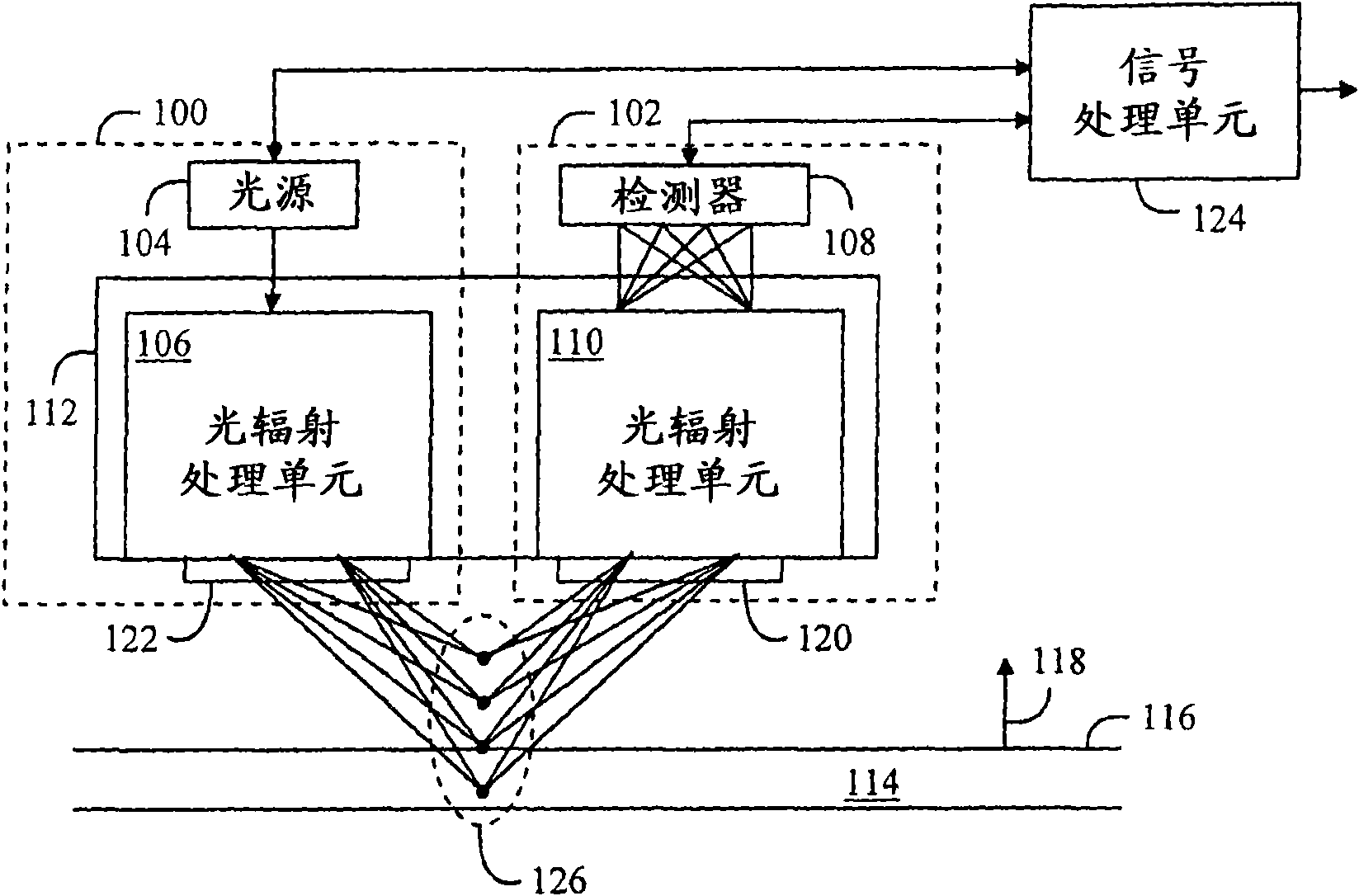
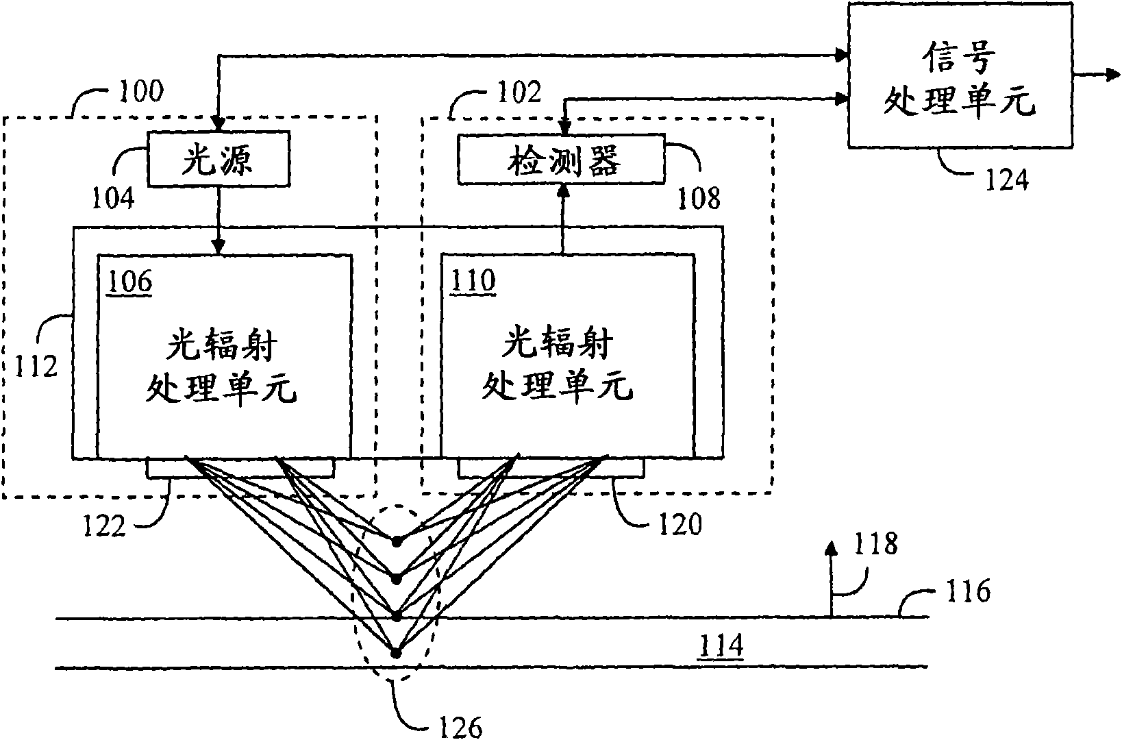
[0028] let's pass now figure 1 Examining the present scheme, in the figure the measuring device comprises a transmitter part 100 and a receiver part 102 separated from each other. The transmitter section 100 includes a light source 104 and a first optical radiation processing section 106 . In this application, optical radiation refers to electromagnetic radiation having a wavelength band between ultraviolet radiation (wavelength approximately 50 nm) and infrared radiation (wavelength approximately 1 mm). The receiver section 102 includes a detector 108 and a second optical radiation processing section 110 . The optical radiation processing sections 106 and 110 fo...


PUM


Abstract

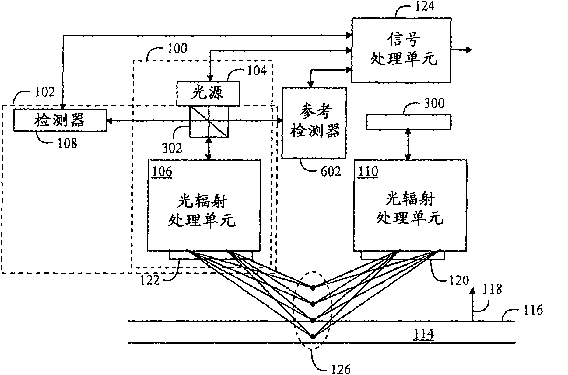
An optical radiation processing unit (112) directs different wavelengths of the optical radiation emitted by an optical source (104) to an object (114) being measured from a direction that differs from the normal (118) of a surface (116) being measured in such a manner that the different wavelengths focus on different heights in the direction of the normal (118) of the surface (116) being measured. A possible polarizer (120, 122) polarizes the reflected radiation in a direction perpendicular to the normal (118) of the surface (116). The optical radiation processing unit (112) directs to a detector (108) polarized optical radiation that it receives from the object (114) being measured. The signal processing unit (124) determines on the basis of a signal provided by the detector (112) from the detected radiation the wavelength on which the intensity of the radiation is the highest, and determines the location of the surface (116) by means of the determined wavelength. When measuring an object (114) from both sides, the thickness of the object (114) being measured is determinable using the locations of the surfaces.

Description

technical field [0001] The invention relates to a method for determining the surface of a measured object, and a method for determining the thickness of a measured object. Furthermore, the invention relates to a measuring device for determining the surface of a measured object, and a measuring device for determining the thickness of a measured object. Background technique [0002] For example, in papermaking, the thickness of the paper is measured from a moving paper web. In this measurement, a scheme in which the sensor of the measuring device contacts the surface of the paper, or a scheme in which the sensor does not contact the surface may be used. Solutions that do not touch the surface include capacitive and optical measurements. Contact of the sensor with the surface being measured may produce surface errors, so solutions in which the sensor contacts the surface of the object being measured are to be avoided. [0003] Optical measurements use color difference to det...

Claims


Application Information

Patent Timeline
Patent Type & Authority Applications(China)
IPC IPC(8): G01B11/06G01N21/25G01S17/32D21F7/06G01B11/14G01N21/21G01N21/55
CPCD21F7/06G01N21/57G01B11/0691G01S7/499G01B2210/50G01N21/41G01S17/46G01B2210/44
Inventor H·克拉内
Owner LEMMAI TECH CO LTD
Learn More