Infrared transmitting or receiving circuit board unit and infrared touch screen

A circuit board unit, infrared technology, applied in electromagnetic receivers, electrical digital data processing, instruments, etc., can solve the problems of insensitivity to touch, lagging response speed, intermittent strokes, etc.

Inactive Publication Date: 2013-03-06
贺伟
View PDF2 Cites 0 Cited by
  • Summary
  • Abstract
  • Description
  • Claims
  • Application Information

AI Technical Summary

Problems solved by technology

At present, it is difficult to produce large-scale and large-scale touch screens, not to mention cutting and splicing circuit boards, which seems impossible
In fact, when the size of the infrared touch screen continues to increase, strict requirements are placed on the scanning speed of the infrared emitting and receiving tubes. If the design cannot meet the required scanning frequency, or the signal cannot be transmitted effectively, this will directly affect the capture. Response speed and use effect, the most obvious is that the strokes may be intermittent when writing, the touch is not sensitive, or the response speed is lagging, or the requirements of the handwriting function cannot be realized
From this point of view, due to the limitations of various technical bottlenecks, whether it can be effective without any influence after cutting and splicing, ensuring high-quality infrared emission and receiving signals to the microprocessor for interception object positioning judgment will become the solution The key to success or failure, it can be seen that it is particularly difficult to design a product that can freely cut the size of the printed circuit board. So far, there is no product on the market that can cut the size of the printed circuit board. Free cutting and splicing infrared touch products

Method used


Image

  • Infrared transmitting or receiving circuit board unit and infrared touch screen
  • Infrared transmitting or receiving circuit board unit and infrared touch screen
  • Infrared transmitting or receiving circuit board unit and infrared touch screen

Examples


Embodiment 1

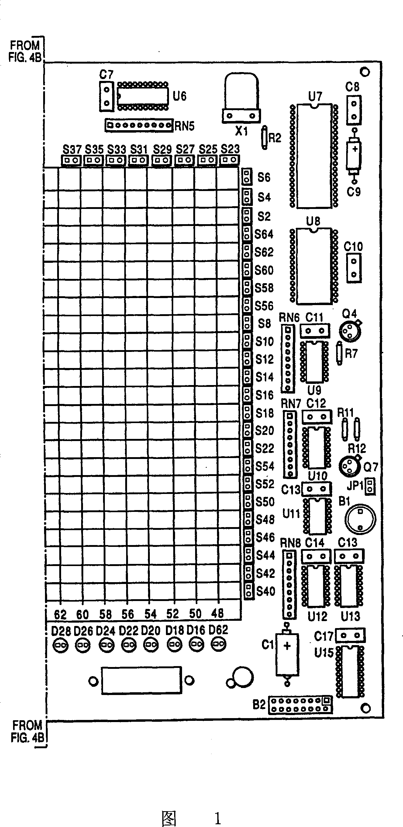
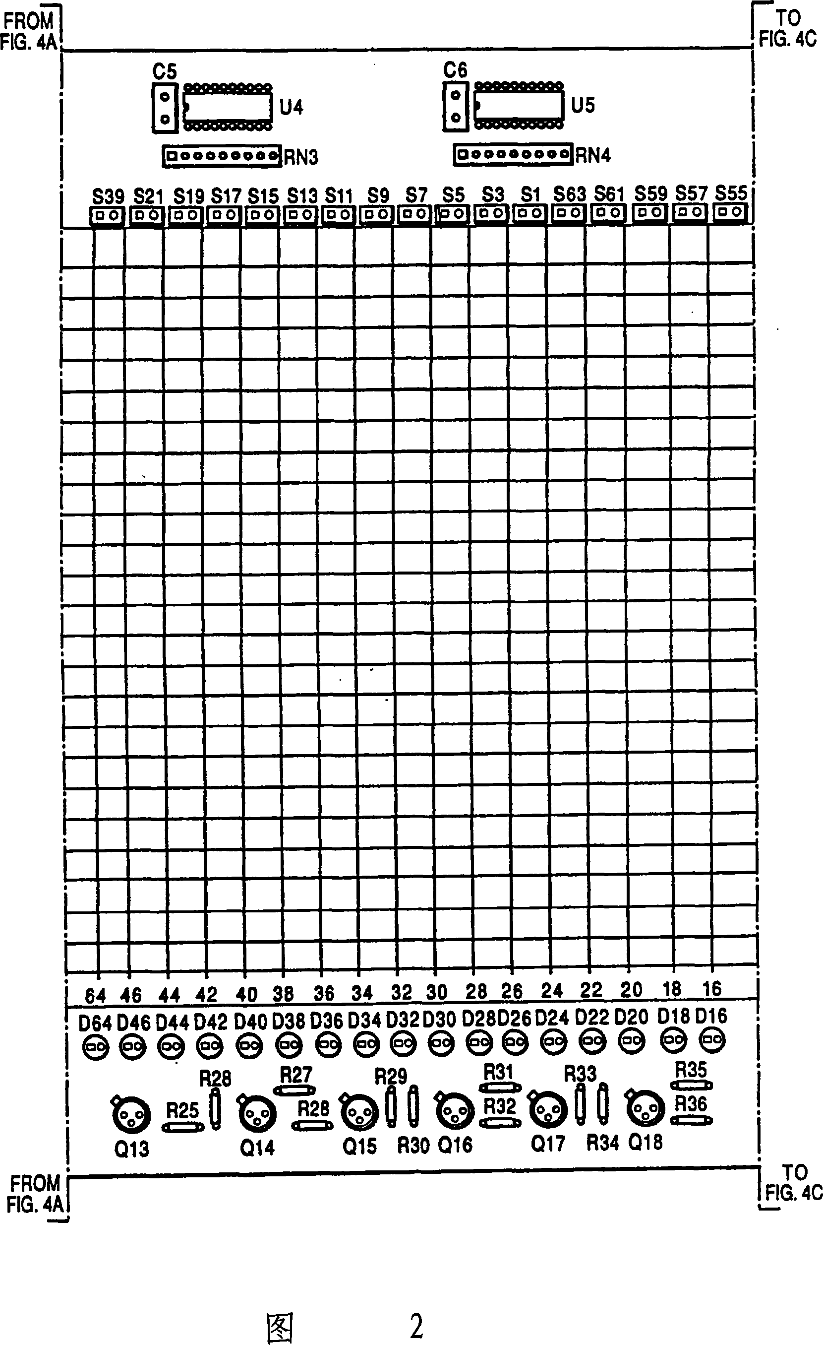
[0049] An infrared touch screen, which includes several infrared emitting or receiving circuit board units provided with an array of infrared emitting or receiving tubes 10, and a controller unit 16 provided with a unit control port;

[0050] The controller unit (CU) 16 includes a microprocessor 28 provided with an enabling control output 36, a clock generator 29, an infrared pulse generator 31 provided with an infrared pulse output 33, and an infrared signal processing unit connected to the microprocessor 28. Device 30, power supply terminal 37 and ground terminal 38, wherein clock generator 29 is connected to microprocessor 28 and is provided with clock signal output terminal 34, and infrared signal processor 30 has infrared ray receiving signal terminal 32;

[0051] Each circuit board unit is provided with a power line 22, a ground wire 23, a clock signal line 20, an enabling control line 24, an infrared pulse signal line 21 and an infrared receiving signal line 19 that run ...

Embodiment 2

[0065] In Embodiment 1, the cutting and splicing methods of the infrared emitting or receiving circuit board unit have been described in detail. In Embodiment 2, the cutting and splicing methods of the circuit board are the same as those in Embodiment 1. The difference is that in the scheme 2, the clock signal lines 20 used to control the row and column drivers are replaced by transmission protocol control lines, such as SMBus, SPI, CAN, QSPI, MICROWIRE, I 2 C, UART and other control lines, or address line control is also available. At the same time, the row and column drivers are also different from the working principle of using clock signals to control the output ports of the row and column drivers described in Scheme 1, but use I / O expanders (I / OExpander), LED drivers (LED drivers) , Multiplexer, Decoder or an integrated circuit with equivalent functions to achieve the purpose of replacing the clock signal line to control the row and column drivers in each circuit board un...


PUM


Abstract

The invention discloses an infrared transmitting or receiving circuit board unit capable of cutting and mutual splicing on a free position as well as an infrared touch screen consisting of the circuit board unit. The circuit board unit is provided with a power cord, an earth wire, a clock signal wire or a transfer protocol control wire, an infrared pulse signal wire and an infrared receiving signal wire, wherein a line driver and a row driver are arranged in the middle of the circuit board unit. The circuit board units can be spliced to form the infrared touch screens of any size and are respectively connected through corresponding ports of a controller unit, thereby carrying out synchronous fractional scanning to effectively improve the scanning speed. The infrared transmitting or receiving circuit board unit does not need to be developed again to the infrared touch screens with different sizes, thereby greatly improving the production efficiency; meanwhile, the circuit board unit has the advantages of flexible selection of splicing points, less restriction on processing conditions and ideal product quality stability and consistency; therefore, the product updating speed can be improved and product types can be increased and expanded without restriction.

Description

technical field [0001] The invention relates to the technical field of a touch device constructed by infrared emitting and receiving photoelectric devices. Background technique [0002] Since the development of infrared touch technology, it has been relatively mature in technology. From a technical point of view, the principle is very simple, but it is particularly difficult to manufacture high-resolution touch screens of various sizes. In the existing technology, such as figure 1 , figure 2 In the shown U.S. Patent No. 5,162,783, all control circuits of the infrared touch device, including infrared emitting and receiving tubes, infrared emitting, receiving circuits and microprocessors, are all integrated on the printed circuit board around the outer frame of the touch screen, and are connected through a The RS232 serial port or USB port is connected to the computer. Since the infrared emitting and receiving tubes must be connected to the scanning circuit, if the circuit ...

Claims


Application Information

Patent Timeline
Patent Type & Authority Patents(China)
IPC IPC(8): G06F3/042H04B10/114H04B10/69
Inventor 贺伟
Owner 贺伟
Why Eureka
Try Eureka