Infrared transmitting or receiving circuit board unit and infrared touch screen
A circuit board unit, infrared technology, applied in electrical components, electromagnetic receivers, electromagnetic wave transmission systems, etc., can solve the problems of intermittent strokes, insensitive touch, and inability to realize handwriting functions.
- Summary
- Abstract
- Description
- Claims
- Application Information
AI Technical Summary
Problems solved by technology
Method used
Image
Examples
Embodiment 1
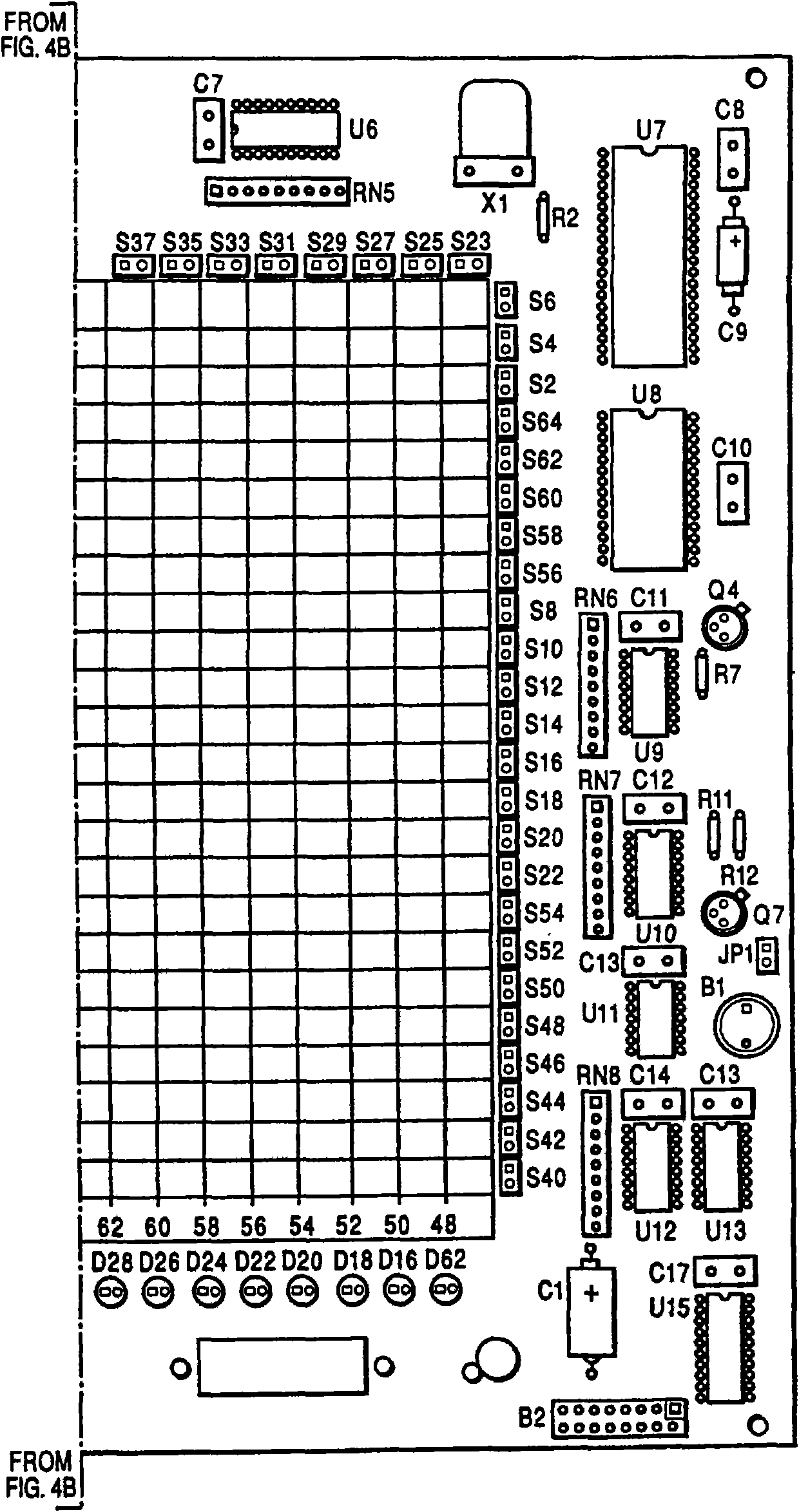
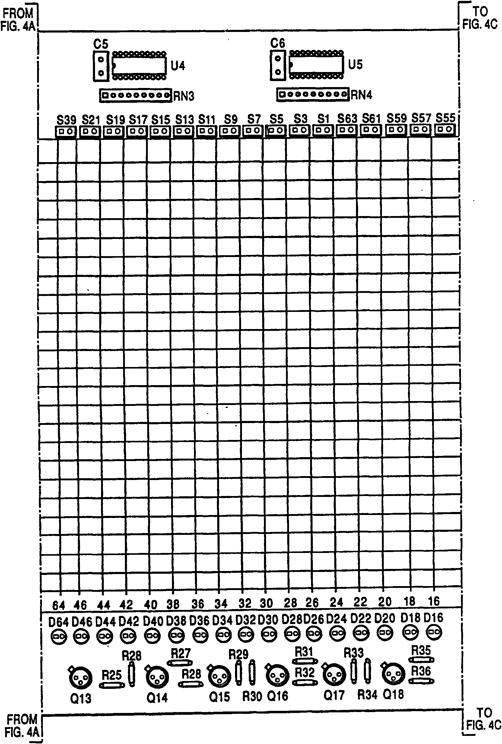
[0049] An infrared touch screen, which includes several infrared emitting or receiving circuit board units provided with an array of infrared emitting or receiving tubes 10, and a controller unit 16 provided with a unit control port;
[0050] The controller unit (CU) 16 includes a microprocessor 28 provided with an enabling control output 36, a clock generator 29, an infrared pulse generator 31 provided with an infrared pulse output 33, and an infrared signal processing unit connected to the microprocessor 28. Device 30, power supply terminal 37 and ground terminal 38, wherein clock generator 29 is connected to microprocessor 28 and is provided with clock signal output terminal 34, and infrared signal processor 30 has infrared ray receiving signal terminal 32;
[0051] Each circuit board unit is provided with a power line 22, a ground wire 23, a clock signal line 20, an enabling control line 24, an infrared pulse signal line 21 and an infrared receiving signal line 19 that run ...
Embodiment 2
[0065] In Embodiment 1, the cutting and splicing methods of the infrared emitting or receiving circuit board unit have been described in detail. In Embodiment 2, the cutting and splicing methods of the circuit board are the same as those in Embodiment 1. The difference is that in the scheme 2, the clock signal lines 20 used to control the row and column drivers are replaced by transmission protocol control lines, such as SMBus, SPI, CAN, QSPI, MICROWIRE, I 2 C, UART and other control lines, or address line control is also available. At the same time, the row and column drivers are also different from the working principle of using clock signals to control the output ports of the row and column drivers described in Scheme 1, but use I / O expanders (I / OExpander), LED drivers (LED drivers) , Multiplexer, Decoder or an integrated circuit with equivalent functions to achieve the purpose of replacing the clock signal line to control the row and column drivers in each circuit board un...
PUM
 Abstract
Description
Claims
Application Information
 - R&D Engineer
- R&D Manager
- IP Professional
- Industry Leading Data Capabilities
- Powerful AI technology
- Patent DNA Extraction
Browse by: Latest US Patents, China's latest patents, Technical Efficacy Thesaurus, Application Domain, Technology Topic, Popular Technical Reports.
© 2024 PatSnap. All rights reserved.Legal|Privacy policy|Modern Slavery Act Transparency Statement|Sitemap|About US| Contact US: help@patsnap.com


