Eureka AIR delivers breakthrough ideas for toughest innovation challenges, trusted by R&D personnel around the world.

Optical film material of lateral light type backlight module

An optical film, backlight module technology, applied in optics, nonlinear optics, components of lighting devices, etc., can solve problems such as cost and manufacturing threshold reduction, cost reduction, etc., to achieve the effect of saving number without affecting brightness

Inactive Publication Date: 2009-09-09
CORETRONIC
View PDF0 Cites 11 Cited by
  • Summary
  • Abstract
  • Description
  • Claims
  • Application Information

AI Technical Summary

Problems solved by technology

[0007] However, backlight module manufacturers are trying their best to reduce costs, and the way to reduce costs is nothing more than simplifying the structure of the backlight module to reduce the number of optical film materials.
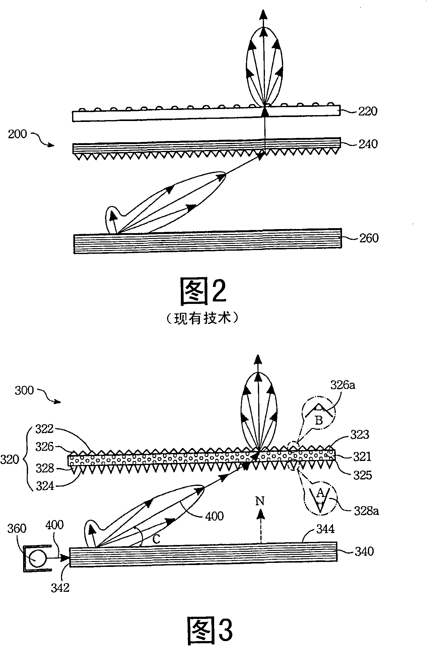
The backlight module 200 in FIG. 2 has not been able to integrate the reverse prism sheet 240 and the diffusion sheet 220, indicating that there is still room for reduction in cost and manufacturing threshold

Method used


Image

  • Optical film material of lateral light type backlight module
  • Optical film material of lateral light type backlight module
  • Optical film material of lateral light type backlight module

Examples


Embodiment Construction

[0022] The aforementioned and other technical content, features and effects of the present invention will be clearly presented in the following detailed description of preferred embodiments in conjunction with the accompanying drawings. The directional terms mentioned in the following embodiments, such as: up, down, left, right, front or back, etc., are only referring to the directions of the drawings. Accordingly, the directional terms are used to illustrate and not to limit the invention.

[0023] Referring to FIG. 3 , the edge-lit backlight module 300 includes an optical film 320 , a light guide plate 340 and a light source 360 ​​. The optical film material 320 has an upper surface 322 and a lower surface 324 . The lower surface 324 is opposite to the upper surface 322 . The upper surface 322 is the surface of the upper prism structure 326 . The lower surface 324 is the surface of the lower prism structure 328 . Between the upper prism structure 326 and the lower prism ...


PUM

PropertyMeasurementUnit
Top angleaaaaaaaaaa
Top angleaaaaaaaaaa

Abstract

The invention relates to an optical film material, which is applied to a lateral light type backlight module. The lateral light type backlight module is provided with a light guide plate used for guiding a main light beam. The light guide plate is provided with a light-emitting face so as to define the direction of a normal. The optical film material comprises a lower prism structure, a middle medium layer and an upper prism structure. The lower prism structure is positioned on the light-emitting face. The middle medium layer is connected with the lower prism structure. The upper prism structure is connected with the middle medium layer, and the middle medium layer is positioned between the upper prism structure and the lower prism structure. When the main light beam is emitted out from the light-emitting face of the light guide plate and passes through the lower prism structure, the main light beam is along with the changed travel direction so as to pass through the middle medium layer. When the main light beam is emitted out from the middle medium layer and passes through the upper prism structure, the main light beam is approximately turned to the direction of the normal from the changed travel direction.

Description

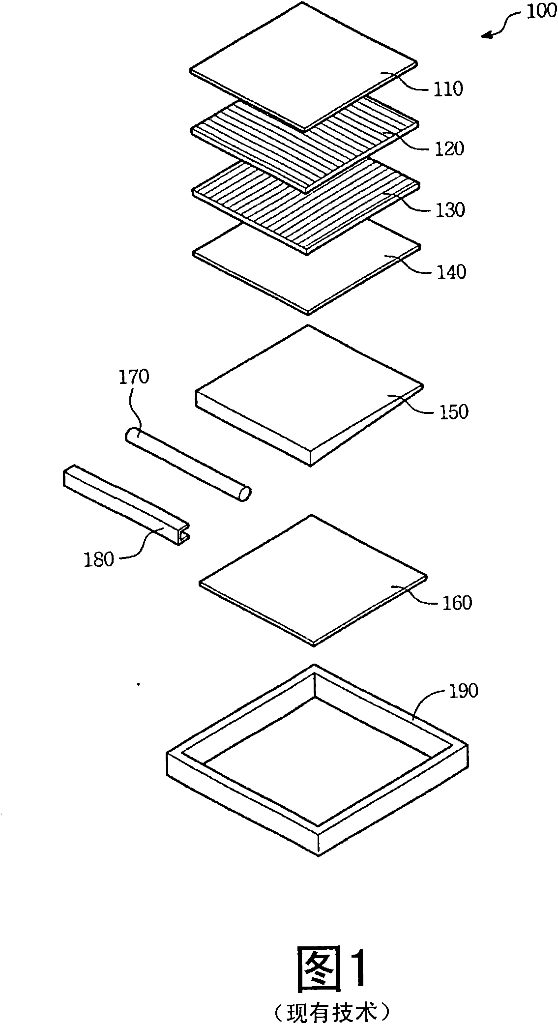
technical field [0001] The invention relates to an optical film material, in particular to an optical film material applied to a side-light backlight module. Background technique [0002] In the edge-lit backlight modules of notebook computers or monitors, optical film materials, such as diffusers and brightness enhancement films, are often used to achieve the effect of concentrating light and increasing brightness. [0003] Referring to FIG. 1 , the existing edge-lit backlight module 100 mainly consists of an upper diffusion sheet 110 , a brightness enhancement film 120 in the X-axis direction, a brightness enhancement film 130 in the Y-axis direction, a lower diffusion sheet 140 , a light guide plate 150 , and a reflection sheet 160 . , a light source 170, a reflector 180 and an outer frame 190. Among them, the upper and lower diffusion sheets 110 and 140, the brightness enhancement films 120 and 130 and other optical film materials and the light guide plate 150 are the m...

Claims


Application Information

Patent Timeline
IPC IPC(8): G02F1/13357G02B5/02F21V5/02
Inventor 萧增科李清祥周文彬臧志仁
Owner CORETRONIC
Why Eureka
Eureka Blog
Learn More