
Heat exchanger

A heat exchanger, a pair of technology, applied in the direction of evaporator/condenser, lighting and heating equipment, refrigeration components, etc., can solve the problems of reduced air volume flowing through the plate, heat exchanger thermal efficiency reduction, etc., to achieve reduction requirements, The effect of reliable connection and simple structure

Active Publication Date: 2009-09-09
SANHUA HANGZHOU MICRO CHANNEL HEAT EXCHANGER +1
View PDF0 Cites 1 Cited by
  • Summary
  • Abstract
  • Description
  • Claims
  • Application Information

AI Technical Summary

Problems solved by technology

Due to the existence of the gap S, in actual use, part of the wind will directly pass through the gap, thereby reducing the amount of air flowing through the plate, causing a corresponding decrease in the thermal efficiency of the heat exchanger

Method used


Image

  • Heat exchanger
  • Heat exchanger
  • Heat exchanger

Examples


Embodiment Construction

[0043] The present embodiment will be described in detail below in conjunction with the accompanying drawings.

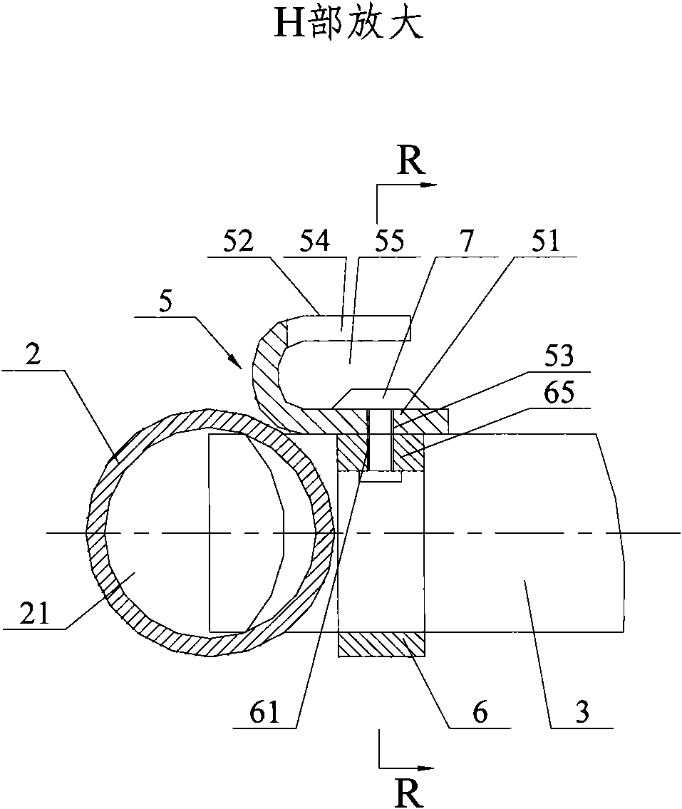
[0044] see figure 2 and Figure 4 , figure 2 is the front view of the heat exchanger provided by the present invention, Figure 4 yes figure 2 top view. As shown in the figure, the heat exchanger 1 of the present invention includes:

[0045] A pair of liquid collecting pipes 2 parallel to each other and separated from each other;

[0046] Several flat flow pipes 3 distributed in parallel, the two ends of the flat flow pipes 3 are respectively connected to the inner cavity 21 of the liquid collecting pipe 2;

[0047] finned plates 4 arranged between adjacent flat flow tubes 3;

[0048] A coupling assembly, the coupling assembly is arranged at the end of the flat flow pipe 3 close to the liquid collecting pipe 2, the coupling assembly includes:

[0049] The coupling part 5 is placed on one side of the flat flow pipe 3 in the width direction;

[0050] At le...


PUM


Abstract

The invention discloses a heat exchanger, which relates to a heat exchange device used in a refrigeration system. The key design point of the heat exchanger comprises: the heat exchanger comprises connecting components which are arranged at the end parts of flat runner pipes close to liquid collecting pipes; the connecting components comprise connecting parts, at least one cushion block and at least one fastener, wherein each connecting part is arranged on one side of the width direction of each of the flat runner pipes; the at least one cushion block is arranged on the other side of the width direction of each of the flat runner pipes; and the least one fastener passes through the clearance between two adjacent flat runner pipes to connect and fix the connecting components and the cushion blocks. Preferably, the supported walls of the connecting components cover the clearance between the liquid collecting pipes and adjacent plate sheets. The heat exchanger has the advantage of simple and reliable structure. As the outside wind blown to the heat exchanger completely passes through the plate sheets between the flat runner pipes for heat exchange, the thermal efficiency of the heat exchanger is improved, and the heat exchanger is particularly suitable for refrigeration air-conditioning units.

Description

technical field [0001] The invention relates to a heat exchange device, in particular to a heat exchanger used in a refrigeration system. Background technique [0002] In the existing refrigeration system, various forms of heat exchangers containing pipes (ie, liquid collection pipes) have roughly the same structure, and their bodies mainly consist of a pair of liquid collection pipes that are parallel to each other and separated from each other. The liquid collection pipes are used to collect heat exchange The refrigerant in other pipes of the heat exchanger or the refrigerant is distributed to other pipes of the heat exchanger; a plurality of flat flow pipes whose two ends are respectively connected to the inner cavity of the liquid collection pipe; and arranged in each pair of flat It is composed of fin-shaped plates between the flat flow tubes; in the liquid collection pipe, there is also a partition that separates its inner cavity into mutually closed chambers to limit ...

Claims


Application Information

Patent Timeline
Patent Type & Authority Applications(China)
IPC IPC(8): F25B39/00
Inventor 和西浩李开泉
Owner SANHUA HANGZHOU MICRO CHANNEL HEAT EXCHANGER
Learn More