Moveable door structure

A technology for sliding doors and door bodies, which is applied to windows/doors, building components, door/window accessories, etc. It can solve the problems of wasting wood resources, consuming a lot of wood, and not having energy-saving and noise-reducing effects, so as to save wood resources Effect

Active Publication Date: 2011-02-02
CHANGSHU ZHONGXINBUILDING MATERIAL CO LTD
View PDF6 Cites 0 Cited by
  • Summary
  • Abstract
  • Description
  • Claims
  • Application Information

AI Technical Summary

Problems solved by technology

[0003] The applicant believes that none of the above-mentioned patents and patent application technologies involves the following technical problems in the current sliding door structure: first, the connection between the vertical frame and the upper and lower frames is unreliable and there is a risk of dismemberment during use; The second is that the vertical frame and the upper and lower frames appear in the form of metal materials such as aluminum extrusions, or in the form of pure wood. It makes up for the lack of the former, but consumes a large amount of wood. For example, in order to connect the door body and the frame body with tenon joint effect, it is necessary to make grooves on the frame body, which not only wastes wood resources, but also requires a lot of processing work; the third is Poor sound insulation, heat insulation and light transmittance, no energy saving and noise reduction effect
[0004] The structure of the sliding door guide device in the prior art also has deficiencies, specifically: when the sliding door is moved to the door frame, it is easy to collide with the door frame

Method used


Image

  • Moveable door structure
  • Moveable door structure
  • Moveable door structure

Examples


Embodiment Construction

[0021] In order to enable the examiners of the patent office, especially the public, to understand the technical essence and beneficial effects of the present invention more clearly, the applicant will describe in detail below in conjunction with the accompanying drawings in the form of embodiments, but none of the descriptions of the embodiments is a description of the present invention. Restriction of the inventive solution, any equivalent transformation made according to the concept of the present invention which is only in form but not in substance shall be regarded as the scope of the technical solution of the present invention.

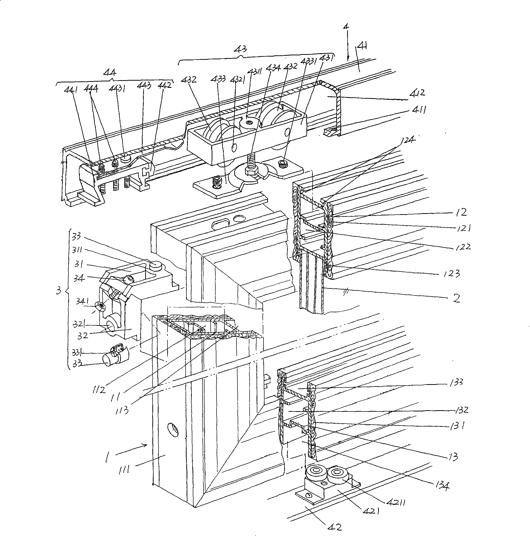
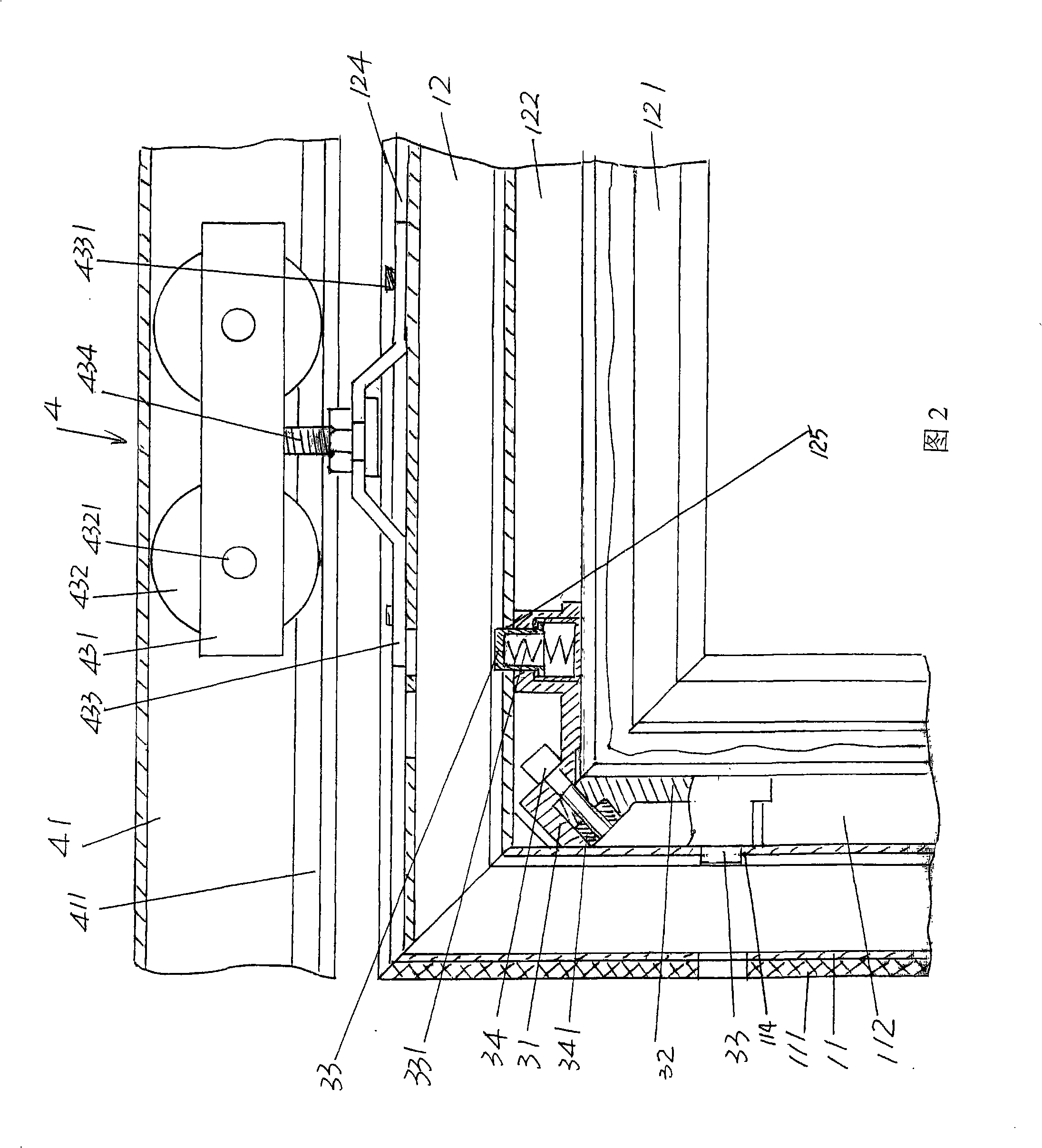
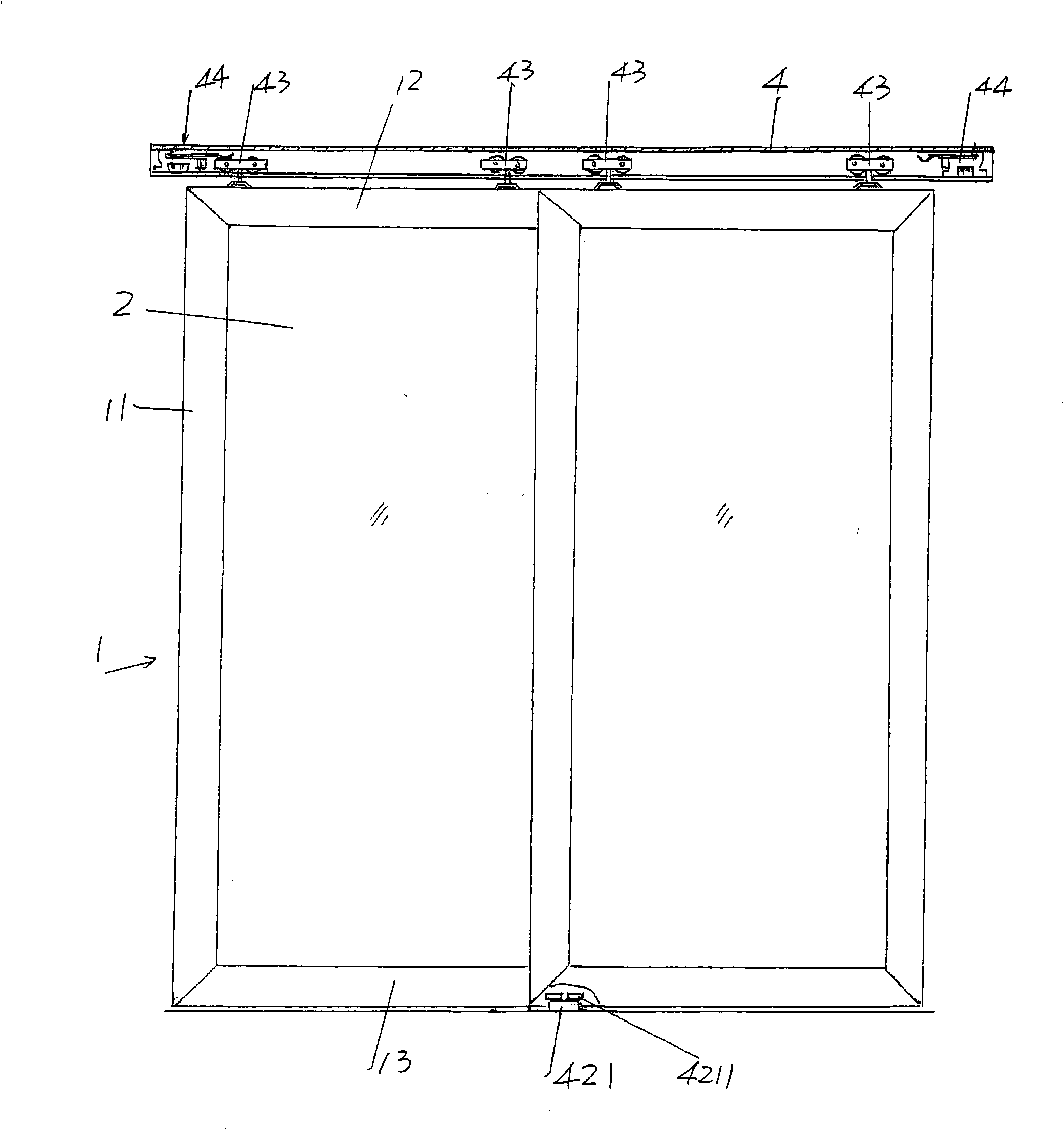
[0022] See figure 1 , according to professional knowledge and common sense of life, there are usually two sliding doors. Although only one is shown in the figure, it will not cause confusion for understanding. Each sliding door is assembled from frame body 1 and door body 2 . In this embodiment, the frame body 1 is composed of a pair of vertica...


PUM


Abstract

A moveable door structure belongs to the technical field of doors and windows of a building and comprises a frame body and a door body arranged on the frame body. The frame body comprises a pair of vertical frames, an upper frame and a lower frame. The upper from is connected with one end of each vertical frame, and the lower frame is connected with the other end of each vertical frame. The door body is embedded on the pair of vertical frames, the upper frame and the lower frame. The moveable door structure is characterized in that the joint parts of the upper frame and the vertical frames aswell as the joint parts of the lower frame and the vertical frames are respectively provided with a transition joint device; the outer walls of the vertical frames are fixedly provided with a first wood protective and decorative plate, respectively; the outer wall of the upper frame is fixedly provided with a second wood protective and decorative plate; the outer wall of the lower frame is fixedly provided with a third wood protective and decorative plate; the door body at least consists of two pieces of doubling embedding glass with cavities or a piece of low-radiation hollow embedding glass; the upper frame is connected with a moveable door guide device; and the lower frame is matched with the moveable door guide device in a sliding manner. The moveable door structure has the advantagesof guaranty of the reliable connection between the upper and the lower frames with the vertical frames, the effect of the combination of softness and rigidity, wood resource saving, energy saving andnoise reduction.

Description

technical field [0001] The invention belongs to the technical field of doors and windows of buildings, and in particular relates to a sliding door structure. Background technique [0002] Sliding doors have been used in buildings for a long time and have been found in documents such as Chinese patent documents. For example, the utility model patent authorization announcement number CN2769460Y recommends the same plane sliding door; and CN2766011Y introduces a built-in sliding door structure; Also as CN201103316Y discloses that there is a novel sandwich sliding door; again as CN201083067Y discloses that there are double-opening and double-closing linkage sliding doors; and then as CN101377109A discloses a glass sliding door device with good sliding performance; more and as the upper hanging translation door recommended by CN201155267Y, etc. [0003] The applicant believes that none of the above-mentioned patents and patent application technologies involves the following tech...

Claims


Application Information

Patent Timeline
Patent Type & Authority Patents(China)
IPC IPC(8): E06B3/968E05F5/02E06B3/46E05D13/00
Inventor 王卫东
Owner CHANGSHU ZHONGXINBUILDING MATERIAL CO LTD
Why Eureka
Try Eureka