
Automatic level-controlling draining dehumidifier and draining method thereof

A dehumidifier and water level technology, which is applied to a dehumidifier with self-controlling water level drainage function, has the field of no water tank, and achieves the effect of reducing the use space of the structure, reducing the space loss and saving materials

Inactive Publication Date: 2009-09-02
NINGBO ERYE & ELECTRONICS
View PDF0 Cites 28 Cited by
  • Summary
  • Abstract
  • Description
  • Claims
  • Application Information

AI Technical Summary

Problems solved by technology

When manual drainage is required, just drain the water at the drain hole

Method used


Image

  • Automatic level-controlling draining dehumidifier and draining method thereof
  • Automatic level-controlling draining dehumidifier and draining method thereof
  • Automatic level-controlling draining dehumidifier and draining method thereof

Examples


Embodiment 1

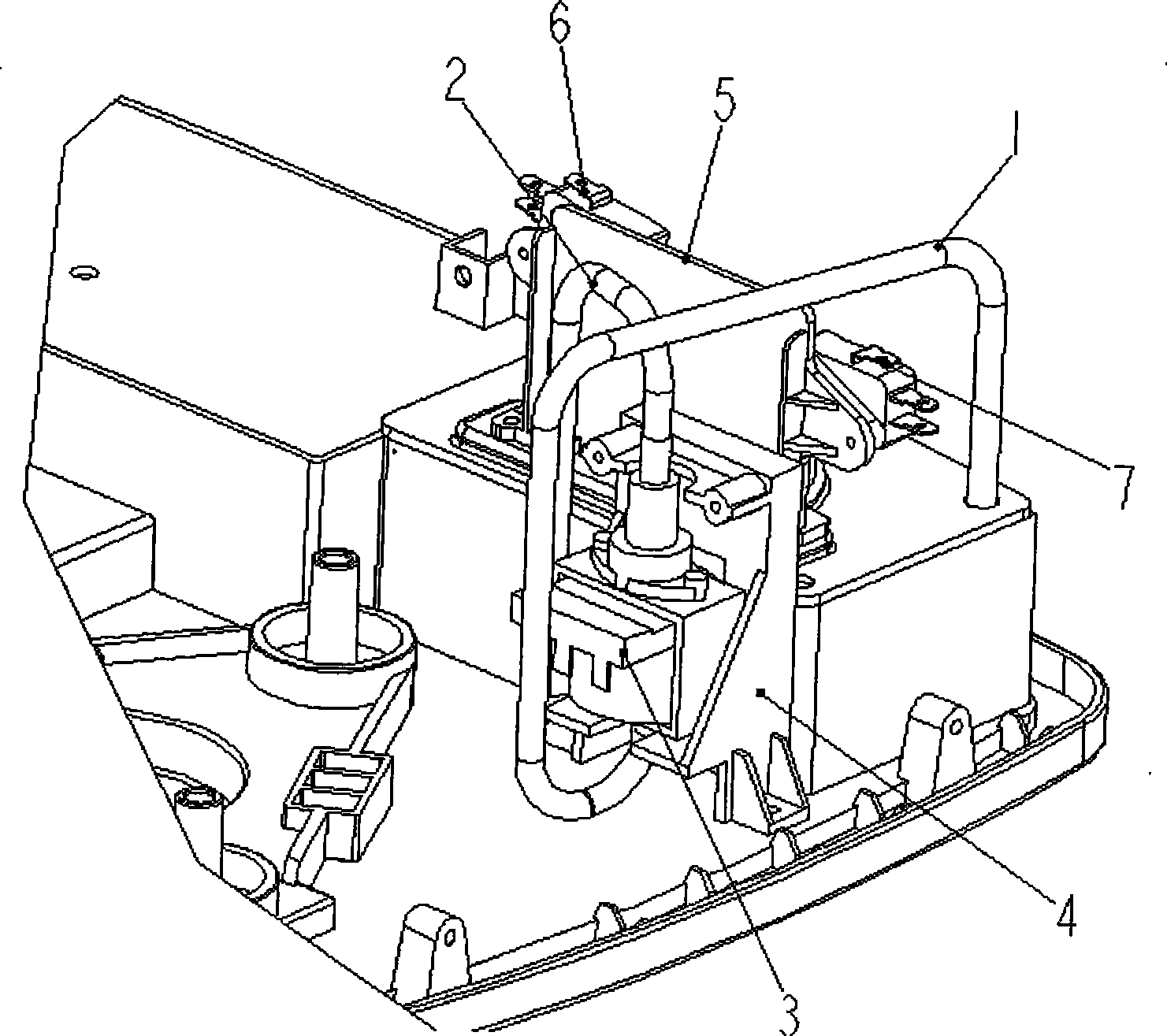
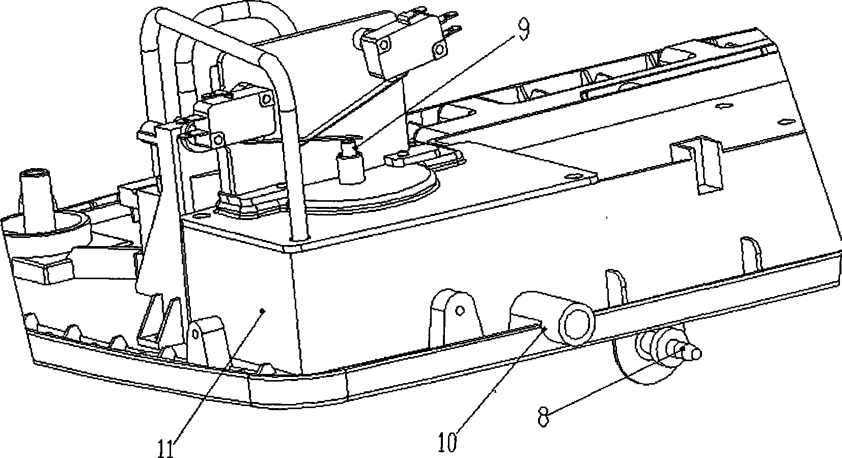
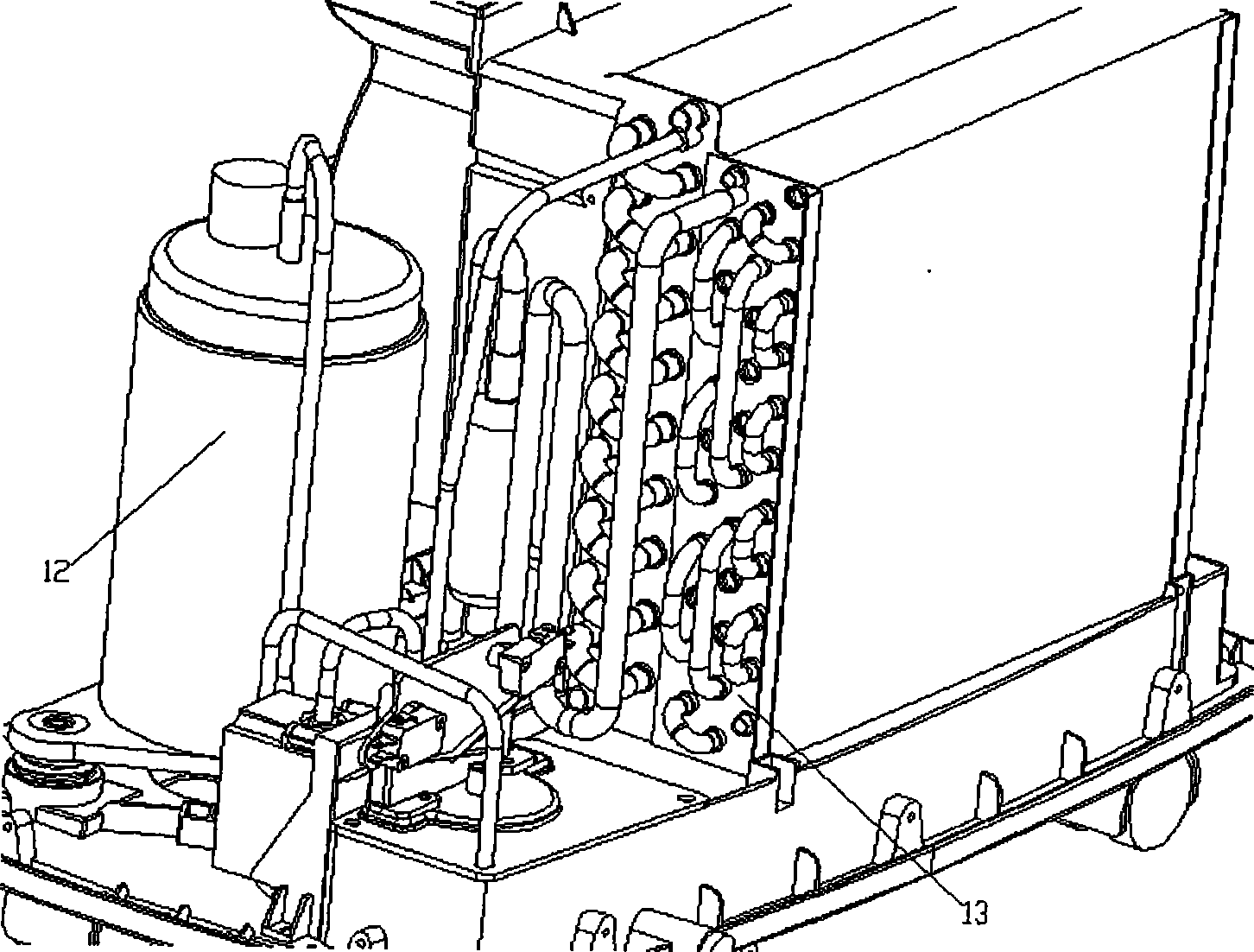
[0035] Such as Figures 1 to 3 As shown, an electromagnetic water pump 3 is set on the side of the water collecting tray, and the float 9 tests the height of the water collection, and then touches the sensor switch fixing part 5 and the full water alarm switch 6 to determine whether the electromagnetic water pump works or stops when the water is full, and the electromagnetic water pump suction pipe 1 One end of the electromagnetic water pump is connected to the suction port of the electromagnetic water pump, and the other end is connected to the water collection tray. A drain hose can be connected to the other end.

[0036] First, preliminarily determine the general positions of the two switches. The full water alarm switch will be a little higher than the pumping alarm switch, and then adjust the length of the float column.

[0037] When the dehumidifier is working, the moisture in the air is condensed by the evaporator and collected in the water storage tank. As the water c...


PUM


Abstract

An automatic level-controlling draining dehumidifier mainly comprises a water pump suction pipe, a water pump drainage pipe, an electromagnetic water pump, a water pump fixing cover, an inductive switch fixing part, a water fullness alarming switch, a pumping alarming switch, a drainage quick adapter assembly, a level measuring floater, a water-collecting tray, an osculum, an osculum plug, a compressor and a heat exchanger; the connection is as follows: one end of the water pump suction pipe is connected with the water-collecting tray and the other end is connected with the electromagnetic water pump; one end of the electromagnetic water pump is connected with the water pump suction pipe; the other end of the water pump drainage pipe is connected with the quick adapter assembly; the level measuring floater is arranged below the water pump fixing cover; and the water fullness alarming switch and the pumping alarming switch are fixed by the inductive switch fixing part. The draining method of the dehumidifier comprises the following steps: one electromagnetic water pump is arranged on the side surface of the water-collecting tray; when the dehumidifier is working, the condensed water is generated by the heat exchanger and falls into the water-collecting tray; the level measuring floater rises slowly under the effect of buoyancy with the increase of water quantity so as to measure the height of the water collected in the water-collecting tray; the floater firstly touches the pumping alarming switch with the rising of level and then the electromagnetic water pump starts to work; the quick adapter at the bottom of a chassis can be connected with a rubber drainage tube with length of about 5M; then the electromagnetic water pump drains the water inside the water-collecting tray out of the room through the water pump suction pipe and the water pump drainage pipe; if the floater touches the pumping alarming switch firstly but the electromagnetic water pump does not work.

Description

technical field [0001] The invention belongs to the technical field of dehumidifiers, and more specifically provides a dehumidifier with no water tank and the function of self-controlling water level drainage. Background technique [0002] Existing dehumidifiers have a water storage tank below the evaporator. When working, the dehumidifier condenses the moisture in the air through the evaporator and collects it in the water storage tank, and then it is manually poured out or drawn out by a simple drain pipe and discharged to the ground. This method is particularly cumbersome when used in storage rooms with strict humidity requirements or in occasions where water needs to be drained to a certain height. [0003] Moreover, the existing dehumidifier sends a warning signal when the water is full, and then the dehumidifier stops working. If the water is not poured out on time, the dehumidifier cannot continue to perform the function of dehumidification. So every time the water...

Claims


Application Information

Patent Timeline
Patent Type & Authority Applications(China)
IPC IPC(8): F24F3/14F24F13/22
Inventor 郑灿镐
Owner NINGBO ERYE & ELECTRONICS
Learn More