
Multi-headed fast tearing butt coupler and fabricated part

A technology for docking buckles and prefabricated parts, which is applied in the field of prefabricated strong fasteners and prefabricated parts manufacturing, and can solve problems such as no impact and unsatisfactory

Active Publication Date: 2011-06-08
周兆弟
View PDF7 Cites 0 Cited by
  • Summary
  • Abstract
  • Description
  • Claims
  • Application Information

AI Technical Summary

Problems solved by technology

[0005] Its objective reality is: in the current detection standard, the detection is the stress transmission, but in the background technology, after the pipe pile after butt joint is pressed into the ground, due to the steel bar (rod) heading and strong There may be a very small amount of poor contact between the connecting rods in the fastener. Although this kind of poor contact is within the scope of reliable docking, it will not have any impact on the quality of butt joints between pipe piles, but due to The pipe piles after docking are pressed into the ground, which cannot be matched with the current testing standards and testing methods, so a very small number of testing results according to the current standards are qualified but not ideal.

Method used


Image

  • Multi-headed fast tearing butt coupler and fabricated part
  • Multi-headed fast tearing butt coupler and fabricated part
  • Multi-headed fast tearing butt coupler and fabricated part

Examples


Embodiment 1

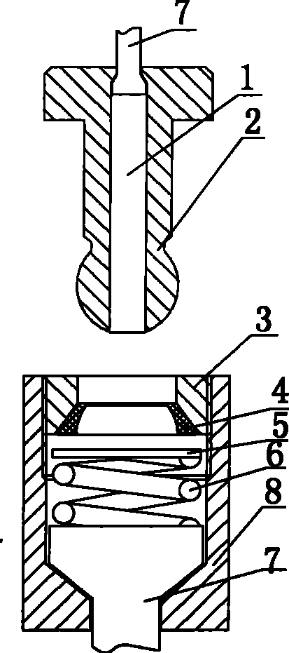
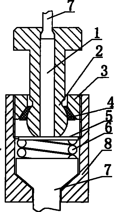
[0017] Embodiment 1: with reference to attached figure 1 and 2 . Multi-head fast strong pull butt joint fastener, which includes a plug 2, the top pull nut 8 is an internal thread structure, the internal thread is a strong wire buckle, a steel hole is opened in the center of the bottom of the cap, and the periphery of the steel hole is a steel bar heading card platform, the plug 2 is a hollow plug, the center of the hollow bottom of the plug 2 is provided with a steel bar hole 1, the periphery of the steel bar hole is a steel bar heading block, and the compression spring 6 is located in the top pull nut 8, One end of the compression spring 6 is located on the steel bar heading card table, and the other end is equipped with a tapered sleeve 4 composed of two or more pieces (generally two pieces form a tapered sleeve-the cavity of the sleeve is tapered and vertically vertical). through, see attached figure 1 and 2 ), the threaded sleeve 3 is screwed in the top pull nut 8 a...

Embodiment 2

[0018] Embodiment 2: On the basis of Embodiment 1, that is to say, the other end of the compression spring 6 is provided with a gasket 5, and the tapered sleeve 4 composed of two or more pieces is located on the gasket 5.

Embodiment 3

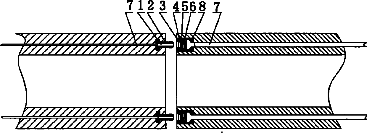
[0019] Embodiment 3: with reference to attached image 3 and 4 . On the basis of Example 1, the prefabricated part is composed of multi-head fast and strong butt joint fasteners. The top pull nut 8 is an internal thread structure, and the internal thread is a strong wire buckle. There is a steel bar hole in the center of the bottom of the cap. The periphery of the steel bar header card platform, the two ends of the prefabricated longitudinal steel bars 7 are upset and clamped on the header card platform, the connector 2 is a hollow connector, and the center of the hollow bottom of the connector is opened. There is a steel bar hole 1, and the periphery of the steel bar hole is a steel bar upsetting card platform. The two ends of the longitudinal steel bar of the prefabricated part are upsetting and clamped on the upsetting card platform. The compression spring 6 is located in the top pull nut 8. The compression spring One end of 6 is located on the head of the steel bar, and ...


PUM


Abstract

The invention relates to a multi-headed fast tearing butt coupler and a butt joint piece, and a fabricated part formed by the multi-headed fast tearing butt coupler, and butt joint structure between tThe invention relates to a multi-headed fast tearing butt coupler and a butt joint piece, and a fabricated part formed by the multi-headed fast tearing butt coupler, and butt joint structure between the fabricated parts, and the invention includes a plug, a support-pulling screw cap is an internal thread structure, the internal thread is a tearing screw thread, the center of the cap bottom is provhe fabricated parts, and the invention includes a plug, a support-pulling screw cap is an internal thread structure, the internal thread is a tearing screw thread, the center of the cap bottom is provided with a steel bar hole, the periphery of the steel bar hole is a steel bar upset head clamping table, the plug is hollow, the center of the hollow bottom of the plug is provided with a steel bar hided with a steel bar hole, the periphery of the steel bar hole is a steel bar upset head clamping table, the plug is hollow, the center of the hollow bottom of the plug is provided with a steel bar hole, the periphery of the steel bar hole is a steel bar upset head clamping table, a pressure spring is positioned inside the support-pulling screw cap, one end of the pressure spring is positioned onole, the periphery of the steel bar hole is a steel bar upset head clamping table, a pressure spring is positioned inside the support-pulling screw cap, one end of the pressure spring is positioned on the steel bar upset head clamping table, the other end thereof is provided with a tapered sleeve formed by two or a plurality of pieces, a screw thread sleeve is rotatably connected inside the supporthe steel bar upset head clamping table, the other end thereof is provided with a tapered sleeve formed by two or a plurality of pieces, a screw thread sleeve is rotatably connected inside the support-pulling screw cap and locates the displacement on the tapered sleeve, the tail part of a connection-peg is connected with the internal thread of a raising-pulling screw cap, and the head part of thet-pulling screw cap and locates the displacement on the tapered sleeve, the tail part of a connection-peg is connected with the internal thread of a raising-pulling screw cap, and the head part of the connection-peg has the ball-lacking shape and is matched with the tampered sleeve in an elastic joint way.connection-peg has the ball-lacking shape and is matched with the tampered sleeve in an elastic joint way.

Description

technical field [0001] The invention relates to a multi-head quick strong pull butt joint fastener and a butt joint, a prefabricated part composed of a multi-head fast strong pull butt joint fastener, and a butt joint structure between the prefabricated part and the prefabricated part, belonging to the prefabricated strong pull fastener and prefabricated field of parts manufacturing. Background technique [0002] The patentee has the authorized announcement number CN100348803C and the name "upper screw and lower top connection pile buckle and prefabricated parts". The pipe pile is composed of longitudinal steel bars, wherein the tension nut and the top tension nut are internal thread structures, and the internal thread is a strong wire buckle. There is a steel bar hole in the center of the bottom of the cap, and the periphery of the steel bar hole is a steel bar heading card platform. The two ends of the longitudinal steel bar of the pipe pile are upset and clamped on the c...

Claims


Application Information

Patent Timeline
Patent Type & Authority Patents(China)
IPC IPC(8): E02D5/52E02D5/58E02D5/30B28B23/08
Inventor 周兆弟
Owner 周兆弟
Learn More