
Method and device for separating oil and water

A technology of oil-water separation and oil-water mixing, which is applied in the direction of separation methods, liquid separation, chemical instruments and methods, etc., and can solve the problems of affecting the separation efficiency of spiral tubes and the deterioration of separation efficiency

Inactive Publication Date: 2009-09-02
CHINA NAT OFFSHORE OIL CORP +1
View PDF1 Cites 15 Cited by
  • Summary
  • Abstract
  • Description
  • Claims
  • Application Information

AI Technical Summary

Problems solved by technology

After the oil separated in the spiral tube is transported to the central liquid collection pipe through the connecting pipe, the fluid flow rate in the spiral tube with equal rotation radius will decrease, and the separation efficiency will gradually deteriorate, and the opening position of the spiral tube will also affect the overall separation efficiency of the spiral tube

Method used


Image

  • Method and device for separating oil and water
  • Method and device for separating oil and water
  • Method and device for separating oil and water

Examples


Embodiment Construction

[0021] The present invention will be described in detail below in conjunction with the accompanying drawings and embodiments.

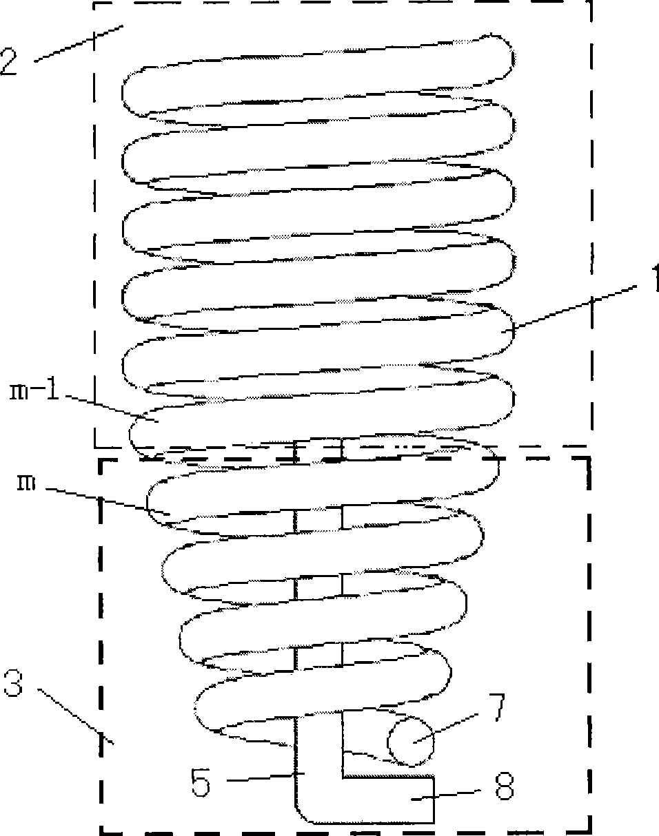
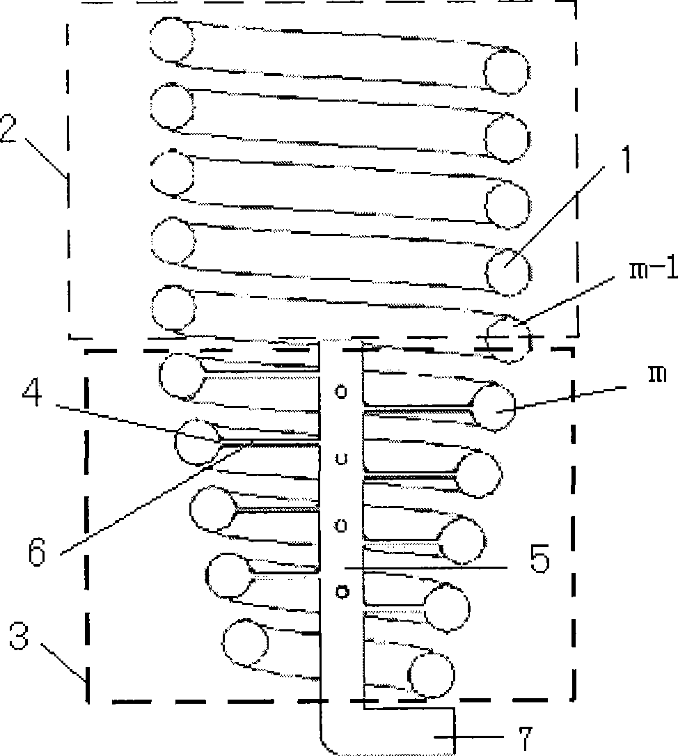
[0022] Such as figure 1 , figure 2 As shown, the present invention is provided with a helical tube 1, and the helical tube 1 is divided into a cylindrical upper tube 2 with an equal radius of rotation and a lower tube 3 with an inverted tapered radius of rotation. A plurality of holes 4 are arranged at intervals inside the tube wall of the lower tube 3, and an oil collecting pipe 5 is arranged in the center of the lower tube 3, and the oil collecting tube 5 is connected with corresponding holes 4 on the inner wall of the lower tube 3 through several connecting pipes 6.

[0023] The present invention makes use of the density difference between oil and water and the centrifugal force generated by the rotating flow of the oil-water mixture in the spiral tube 1, so that the oil-water mixture gradually separates in the upper tube 2 and enters the lower t...


PUM


Abstract

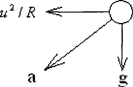
The invention relates to a method and a device for separating oil and water. The method comprises the following steps: a spiral pipe is divided into an upper pipe with the equal turning radius and a lower pipe with the variable turning radius, the upper pipe and the lower pipe are communicated in an integrative mode, the lower pipe is designed into a reversed cone shape, the inner side of the pipe wall of the lower pipe is provided with a plurality of holes at intervals, the center of the lower pipe is provided with an oil collecting pipe which is connected with the corresponding holes through a plurality of connecting pipes, water-phase liquid with larger density moves outside the pipe wall of the lower pipe by using the density difference between oil and water and centrifugal force generated by the spiral flow of oil-water mixed liquid in the spiral pipe, oil-phase liquid collects towards the inner side of the pipe wall of the lower pipe under the pressure function of the water-phrase liquid, meanwhile, the turning radius of the lower pipe is gradually reduced, under the condition that the flow speed of the oil-water mixed liquid is gradually reduced, the centrifugal acceleration is stably maintained, and the separated water-phrase liquid and oil-phrase liquid respectively flow out through a water-phrase liquid outlet arranged at the bottom of the lower pipe and an oil-phrase liquid outlet arranged at the bottom of the oil collecting pipe. The invention can be widely used for various oil-gas field separating systems.

Description

technical field [0001] The invention relates to a method for separating oil-water two-phase mixed liquid, in particular to an oil-water separation method and device used in offshore production platforms, underwater production systems and onshore oil and gas field separation systems. Background technique [0002] At present, in the production process of offshore oil and gas fields and onshore oil and gas fields, the oil-water separation process occupies a very important position. As a new separation technology, the spiral tube separation technology has not been widely used in industry. In a utility model patent "a composite oil-water separation device" (patent publication number: CN 201101907Y) of the Institute of Mechanics of the Chinese Academy of Sciences, the spiral tube separation technology is combined with other separation technologies in the separator for the first time. The method of opening holes on the outer wall to release the water phase realizes the separation o...

Claims


Application Information

Patent Timeline
IPC IPC(8): B01D17/038
Inventor 王涛李清平
Owner CHINA NAT OFFSHORE OIL CORP
Learn More