connection socket

A technology of sockets and connecting parts, which is applied in the direction of connection, fixed connection, parts of connection devices, etc.

Inactive Publication Date: 2011-12-28
SMK CO LTD
View PDF4 Cites 0 Cited by
  • Summary
  • Abstract
  • Description
  • Claims
  • Application Information

AI Technical Summary

Problems solved by technology

[0027] In addition, since the contact portion 228 becomes a free end and moves without restriction when fitting, the contact with the contact portion 228 is good, so it has the function of contacting the plug. Point 260 is provided with a second spring contact piece 264 with a spring force, and must be formed in such a way as to obtain good contact

Method used


Image

  • connection socket
  • connection socket
  • connection socket

Examples


Embodiment 1

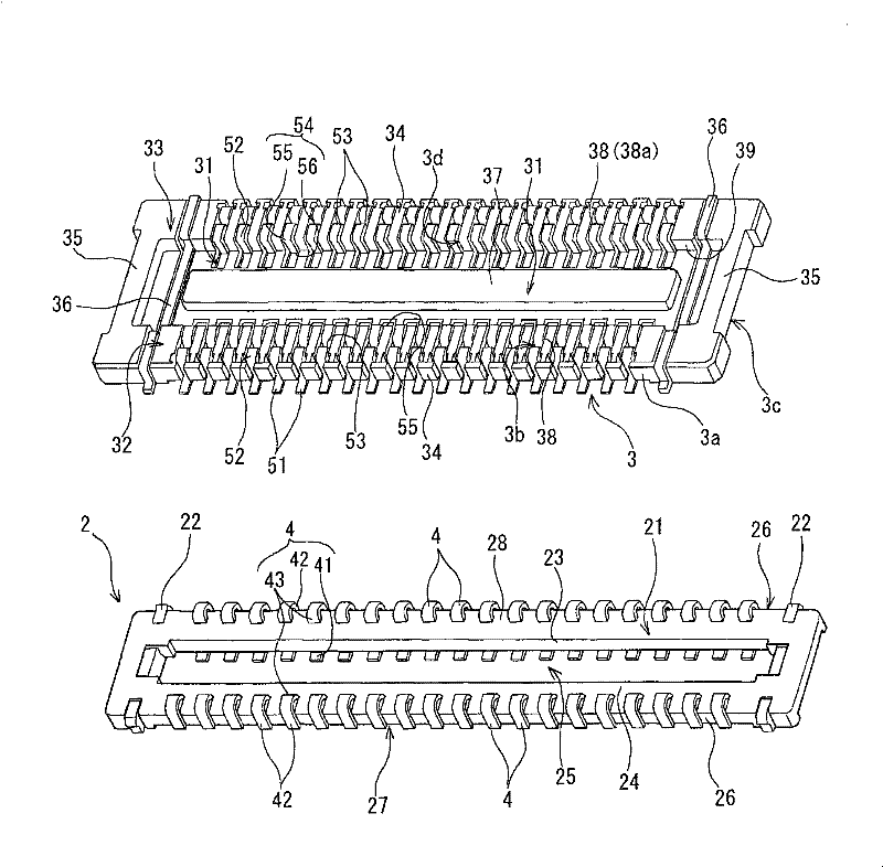
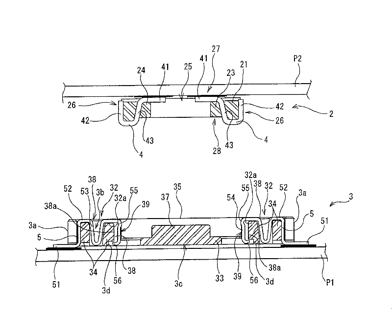
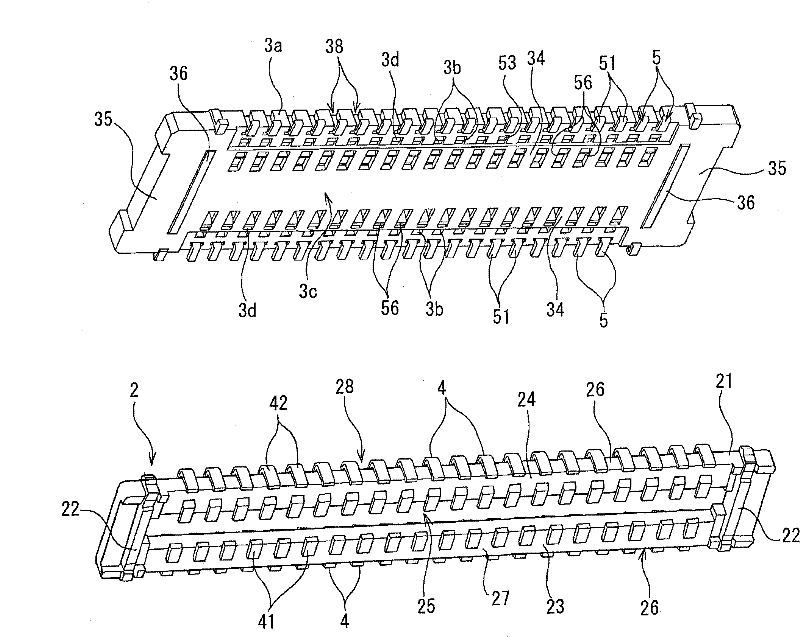
[0066] Embodiment 1 of the present invention will be described below with reference to the drawings. figure 1 is a perspective explanatory view showing Embodiment 1 of the present invention, figure 2 It is a central sectional explanatory view showing Embodiment 1 of the present invention, image 3 is a perspective explanatory view showing Embodiment 1 of the present invention, Figure 4 It is a central sectional explanatory view showing the fitting state of Example 1.

[0067] Reference numeral 1 is a board-to-board connector as Embodiment 1 of the present invention. Connector 1 (hereinafter simply referred to as connector 1) is composed of a plug 2 mounted on a second printed wiring board P2 and a connecting socket 3 mounted on a first printed wiring board P1 as a first connection object (hereinafter referred to as The socket 3) is configured to connect the pin 2 to the socket 3 and to electrically connect the first printed wiring board P1 and the second printed wiring b...

Embodiment 2

[0089] In the first embodiment described above, the connection connector 1 is used to electrically connect the first printed wiring board P1 and the second printed wiring board P2. Example 2 of the structure using the plug 2 as an electronic module as an electronic component is connected to P1.

[0090] Figure 5 It is a perspective explanatory drawing which shows Example 2.

[0091] In the case where the electronic module 2a is formed as a plug and must be connected to the printed wiring board as in Embodiment 2, it is because the electronic module 2a is afraid of heat and has low heat resistance, so it cannot withstand heat such as soldering and when it is repaired. Easy attachment and detachment is necessary and the fixing to the printed wiring board by a fixing method such as soldering is not appropriate. Of course, it can also be used in other cases.

[0092] In the second embodiment, the electronic module 2 a is provided with the latch contacts 4 similarly to the firs...


PUM


Abstract

The present invention provides a board-to-board connector that can further reduce its profile. The socket contact (5), the front end of the plug connection part (54) is located in the insertion depth part and forms a contact deformation prevention part (56), and the plug contact part (55) is protruded on the side of the plug connection part insertion port, and the middle part (52) Form the spring portion (53), form the fitting recess (31) on the socket housing (33), the fixed portion (34) is provided with the insertion hole (3b) that can be inserted into the spring portion, and insert it into the inner surface of the fixed portion One side of the depth part is provided with a notch (3d) to prevent the contact deformation piece from advancing and retreating. The latch (2) is composed of a latch housing (21) and a latch contact (4). One end of the latch contact (4) is located on the latch Outside the housing (21), the other end is located on the side of the plug housing (21) opposite to the plug contact and forms a socket contact portion (42), and the middle portion forms a fixed portion (43) fixed on the plug housing.

Description

technical field [0001] The present invention relates to a connection socket used in a connection connector capable of electrically connecting printed wiring boards to each other or electrically connecting an electrical module to the printed wiring board. Background technique [0002] Although electronic equipment such as household appliances is provided with printed wiring boards on which electronic components are mounted to form the equipment, since electronic components are mounted on only one printed wiring board, the area of ​​the substrate increases, so there is a possibility that multiple small substrates are stacked and arranged. The condition that constitutes the device. In this case, it is necessary to electrically connect the overlapping printed wiring boards to each other using a plurality of connection terminals, and a multi-pole connector is used for board-to-board connection for electrically connecting the printed wiring boards to each other. [0003] Connecto...

Claims


Application Information

Patent Timeline
Patent Type & Authority Patents(China)
IPC IPC(8): H01R12/51H01R12/52H01R13/193H01R33/76
CPCH01R12/52H01R12/716H01R13/26H01R13/639
Inventor 浅井清大泽文雄
Owner SMK CO LTD
Why Eureka
Try Eureka