Method for detecting optical photograph of large mold casting blank

A technology of optical photography and detection methods, applied in the direction of using optical devices, measuring devices, instruments, etc., can solve problems such as tool wear, long inspection time, and decreased precision of processing equipment, so as to reduce cost consumption, speed up production cycle, The effect of improving operation time

Inactive Publication Date: 2009-08-26
CHINA FIRST AUTOMOBILE +1
View PDF6 Cites 10 Cited by
  • Summary
  • Abstract
  • Description
  • Claims
  • Application Information

AI Technical Summary

Problems solved by technology

After alignment, check the machining allowance of the casting through the test tool of the machine tool. The inspection time for large workpieces is very long, and it is easy to miss. Occasionally, there will be tool collision, tool wear, workpiece scrapping, and the accuracy of processing equipment will decrease, which will increase the cost while affecting the production cycle of the workpiece.

Method used


Image

  • Method for detecting optical photograph of large mold casting blank
  • Method for detecting optical photograph of large mold casting blank
  • Method for detecting optical photograph of large mold casting blank

Examples


Embodiment 1

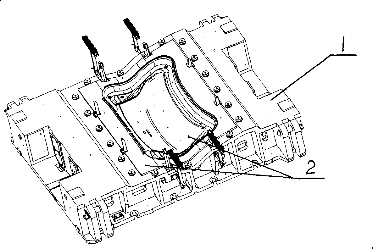
[0012] Such as figure 1 As shown, the entity of casting 1 should be opened before work to fully confirm the shape, size, processing area, non-processing area and related structure positions of the entity. Then paste the processed profile, interference surface, boss formed during the casting process, and peripheral non-processed surface of the workpiece 2; collect data on all processed profiles of the casting blank; ensure that the final data deviation of the collected points is less than 0.5 pixels , The scale deviation is less than 0.15mm, this casting is about 1000 points. After sticking point 2, check the entire casting, and find out if there are any omissions and add them.

Embodiment 2

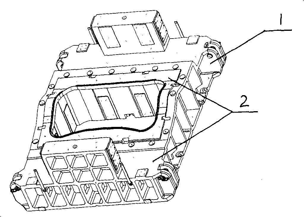
[0014] Such as figure 2 As shown, the entity of casting 1 should be opened before work to fully confirm the shape, size, processing area, non-processing area and related structure positions of the entity. Then paste the processed profile, interference surface, boss formed during the casting process, and peripheral non-processed surface of the workpiece 2; collect data on all processed profiles of the casting blank; ensure that the final data deviation of the collected points is less than 0.5 pixels , The scale deviation is less than 0.15mm, this casting is about 1000 points. After sticking point 2, check the entire casting, and find out if there are any omissions and add them.

Embodiment 3

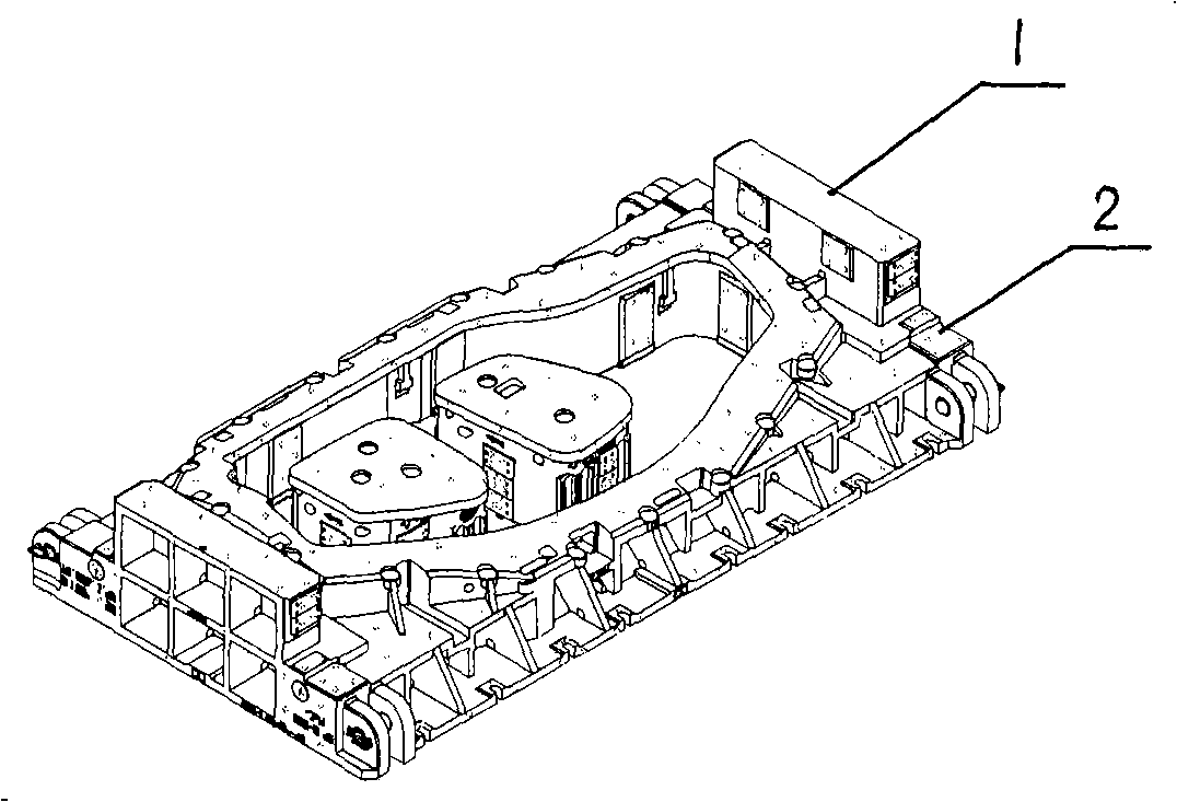
[0016] Such as image 3 As shown, the entity of casting 1 should be opened before work to fully confirm the shape, size, processing area, non-processing area and related structure positions of the entity. Then paste the processed profile, interference surface, boss formed during the casting process, and peripheral non-processed surface of the workpiece 2; collect data on all processed profiles of the casting blank; ensure that the final data deviation of the collected points is less than 0.5 pixels , The scale deviation is less than 0.15mm, this casting is about 1000 points. After sticking point 2, check the entire casting, and find out if there are any omissions and add them.

[0017] Determine the alignment datum for CNC machining, input the CAD data into the alignment environment in the center coordinate system of the die, and ensure the same datum as the CNC machining. Create a coordinate system 3-2-1 for the collected data, and require the bottom surface of the casting to be l...


PUM


Abstract

The invention relates to a method for detecting an optical photograph of a large mold casting blank. The method is characterized in that a lug boss and a peripheral unfinished surface formed by a workpiece are subjected to bulge application; all processing molding surfaces are subjected to data acquisition; a system is established for acquired 3D points, and is compared with the prior theory three-dimensional design data; finally, a digital control processing alignment standard report is released. Under a report chart environment, each direction required in digital control processing is standardized, generally, display of the standard is required to be determined by trial cutting on a machine tool, and theoretical coordinate values, offset directions and dimensions of the coordinates are displayed to be used for digital control processing alignment and standard determination. The method accurately determines the digital control processing standard, reduces load of the machine tool and time for aligning the center by digital control equipment, and accelerates cycle of cast output. A digital control programming staff can reasonably program a digital control processing program through allowance deviation data, thereby improving effective operation time of the digital control machine tool, reducing consumption of cost, improving working efficiency of digital control processing while ensuring the quality of digital control processing, and accelerating the output cycle of cast blank.

Description

Technical field [0001] The invention relates to an optical photographic inspection method of a large mold casting blank, which detects the margin of the large mold casting blank by using an optical detection device. technical background [0002] With the improvement of the quality of mold products and the acceleration of production progress, there are higher requirements for the quality of castings and the production cycle. However, in the past, the castings were directly on the CNC machine tool, and the CNC machining center was determined by the CNC machine tool. This process takes a long time. After aligning, check the machining allowance of the casting through the form of machine tool test. The inspection time for large workpieces is very long, and it is easy to miss. If the interference profile and the convex boss during casting cannot be found in time during CNC machining, the machining When the tool hits, there are phenomena such as tool wear, workpiece scrapping, and reduc...

Claims


Application Information

Patent Timeline
Patent Type & Authority Applications(China)
IPC IPC(8): G01B11/24
Inventor 单堃李悦姚胜谢韬
Owner CHINA FIRST AUTOMOBILE
Why Eureka
Try Eureka