Orifice plate type rock surface roughness mechanical measuring apparatus

A surface roughness and measurement technology, applied in the direction of mechanical roughness/irregularity measurement, etc., can solve the problems of positioning error, expensive equipment, affecting the accuracy of the measured surface roughness, etc., and achieve the effect of accurate positioning

Inactive Publication Date: 2009-08-26
INST OF GEOLOGY & GEOPHYSICS CHINESE ACAD OF SCI
View PDF0 Cites 10 Cited by
  • Summary
  • Abstract
  • Description
  • Claims
  • Application Information

AI Technical Summary

Problems solved by technology

[0011] For this measurement method, the advantages are intuitive and convenient, but there are four shortcomings: first, the measurement accuracy of the steel needle is low, which is definitely lower than its sensitivity of 1mm
Second, the accuracy of the measured surface roughness is affected because the distance between the measuring holes in the bar is large (50mm), that is, the density of the measuring holes is small; third, installing multiple bars on the same plane does not easy, making the measurement time longer; fourth, from Image 6 It can also be seen that there is a possibility of varying degrees of damage to the measured object when installing horizontal bars and using steel needles to measure and read.
As far as this type of instrument is concerned, its advantages are high measurement accuracy and convenient data processing, etc., but the biggest problem is that it is difficult to carry out on-site measurement at the engineering site
In addition, the equipment used is also more expensive than other methods
[0014] From the above analysis, it can be seen that the precision of rock surface roughness measurement instruments that can be used in the field is low, and there is a large error in the positioning of the measured point plane position

Method used


Image

  • Orifice plate type rock surface roughness mechanical measuring apparatus
  • Orifice plate type rock surface roughness mechanical measuring apparatus
  • Orifice plate type rock surface roughness mechanical measuring apparatus

Examples


Embodiment Construction

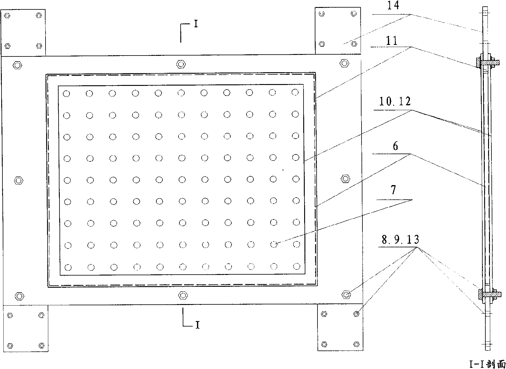
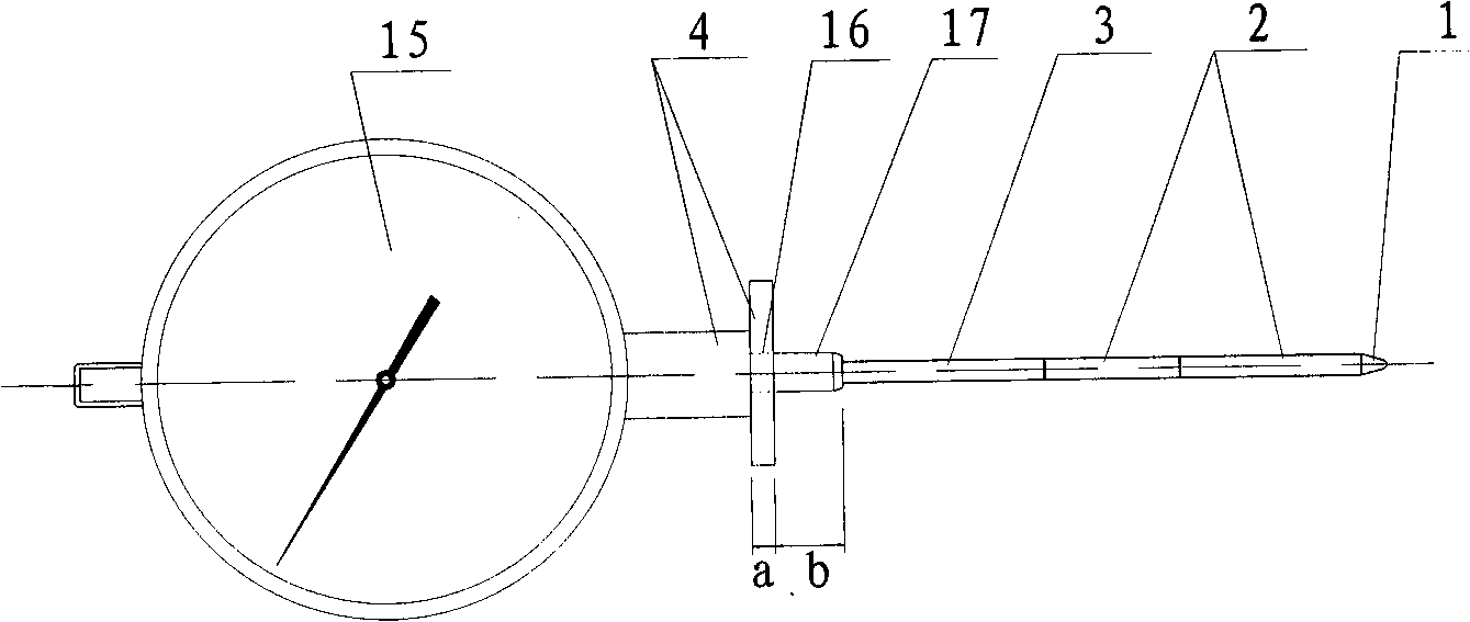
[0041] The invention provides a method for measuring rock surface roughness. The invention mainly includes a transparent test plate 6 with hole group distribution, three-layer protective frames 10-12, a strip joint plate 21, a right-angle joint plate 22, a frame-plate joint 14, and a hundred sub-table 5. Refer below Figure 1-Figure 5 And according to the manufacture and measurement process of the embodiment, the measurement method of the invention is described in detail.

[0042] In general, the length and width of the transparent measuring board are equal to (or slightly less than) the length and width of the hollow part of the middle protective frame 11, and greater than the length and width of the upper and lower protective frames 10 and 12 hollow parts, and its thickness is equal to ( Or slightly less than) the thickness of the middle layer protective frame 11, so the transparent measuring board 6 can be completely fixed by the upper, middle and lower three layers of pr...


PUM


Abstract

The invention discloses a method for measuring rock surface roughness, which includes steps of fixing a transparent measuring plate which is used as measurement relative plane and is studded with measuring holes according to certain manner on a position a certain distance from surface of measured object by auxiliary parts such as a protection frame and a connection plate; sequentially inserting measuring rods of a dial gauge with a measuring holder into the measuring holes of the transparent measuring plate, making the measuring holder fixed on shaft neck of the dial gauge impact the transparent measuring plate, making measuring head of the dial gauge butt against certain point on the surface of the measured object and obtaining reading which is the relative distance from the transparent measuring plate to the measured point; and drafting roughness three dimensional chart of the measured object and roughness profile cut along some profiles by aid of computer and using relative distance obtained in the measuring holes. The invention has advantages of high measurement precision, strong on-site adaptation capability, accurate measuring point positioning and higher measuring point density.

Description

technical field [0001] The invention relates to a method for measuring rock surface roughness, in particular to a mechanical measurement method. Background technique [0002] For modern rock engineering, the roughness of rock surface is a major concern of scientific researchers, engineering design and construction workers. The roughness of the rock surface is directly related to the research on the weathering degree and shear strength of the rock. The former has a direct effect on describing and predicting the weathering speed of rocks, and is of great significance to the study of geomorphology, while the latter involves the current strength of the rock surface at that place, which can be used for theoretical prediction of shear strength. For ancient rock engineering, the research on the degree of weathering and shear strength of the above-mentioned rock surface will also involve the protection of these immovable cultural relics of ancient rock engineering. Therefore, the ...

Claims


Application Information

Patent Timeline
IPC IPC(8): G01B5/28
Inventor 张中俭杨志法张路青刘恩聪付燕
Owner INST OF GEOLOGY & GEOPHYSICS CHINESE ACAD OF SCI
Why Eureka
Try Eureka