
Metal mixing device

A technology of mixing iron and iron mouth, applied in the field of metallurgical steelmaking accessories, can solve the problems of affecting the speed of the new baking furnace, preventing the evaporation of water, and wasting the energy of the baking furnace.

Inactive Publication Date: 2009-08-26
HEBEI WENFENG STEEL & IRON
View PDF0 Cites 0 Cited by
  • Summary
  • Abstract
  • Description
  • Claims
  • Application Information

AI Technical Summary

Problems solved by technology

[0004] For the mixed iron furnace with a fully enclosed furnace shell in the shape of a garden barrel, the iron plate of the furnace shell has the disadvantage of preventing the moisture in the refractory from evaporating when the new furnace is baking, especially in winter, the water vapor cannot condense on the inner layer of the iron plate. Dissipate as soon as possible, affecting the speed of baking a new oven and wasting energy in the oven

Method used


Image

  • Metal mixing device
  • Metal mixing device
  • Metal mixing device

Examples


Embodiment Construction

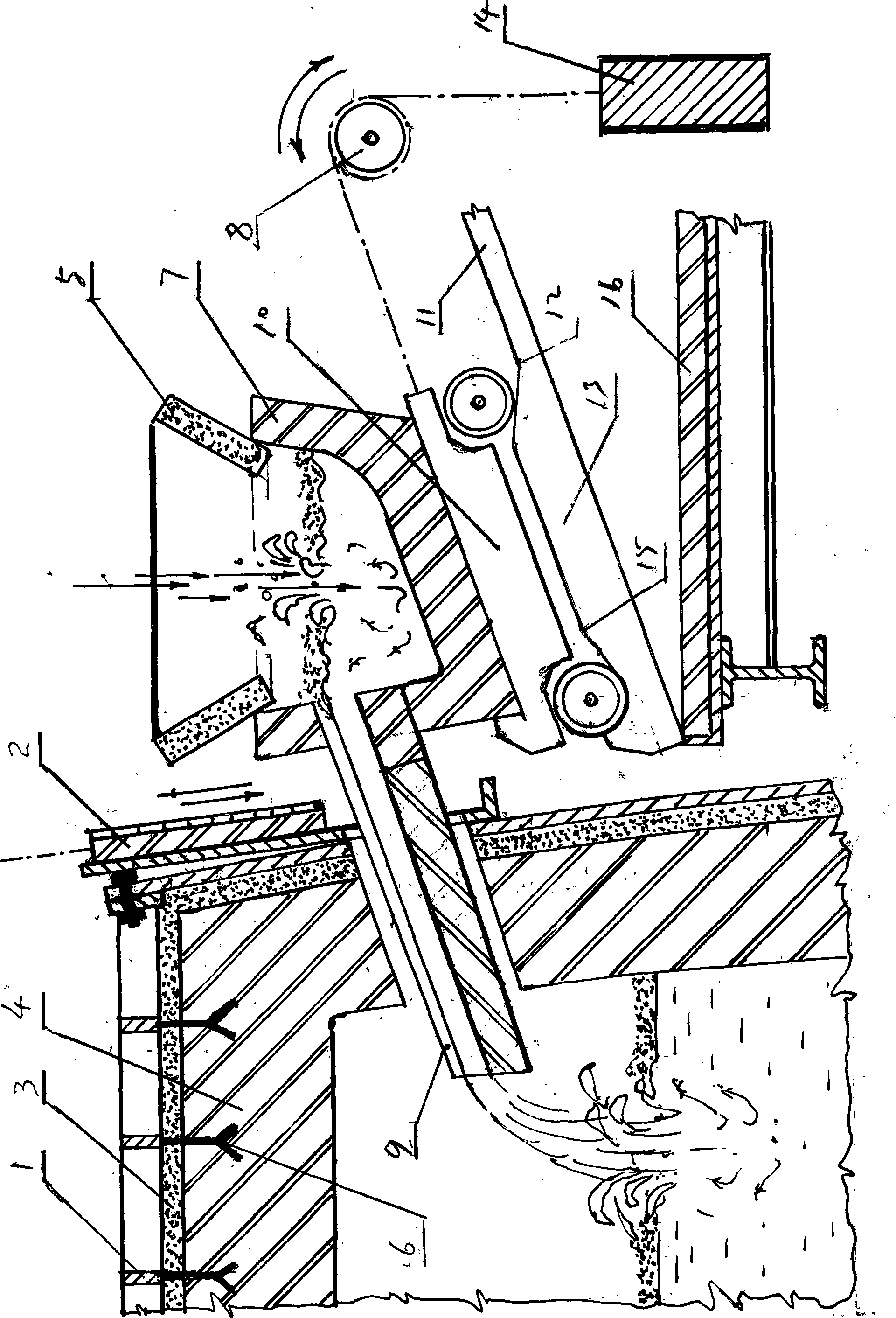
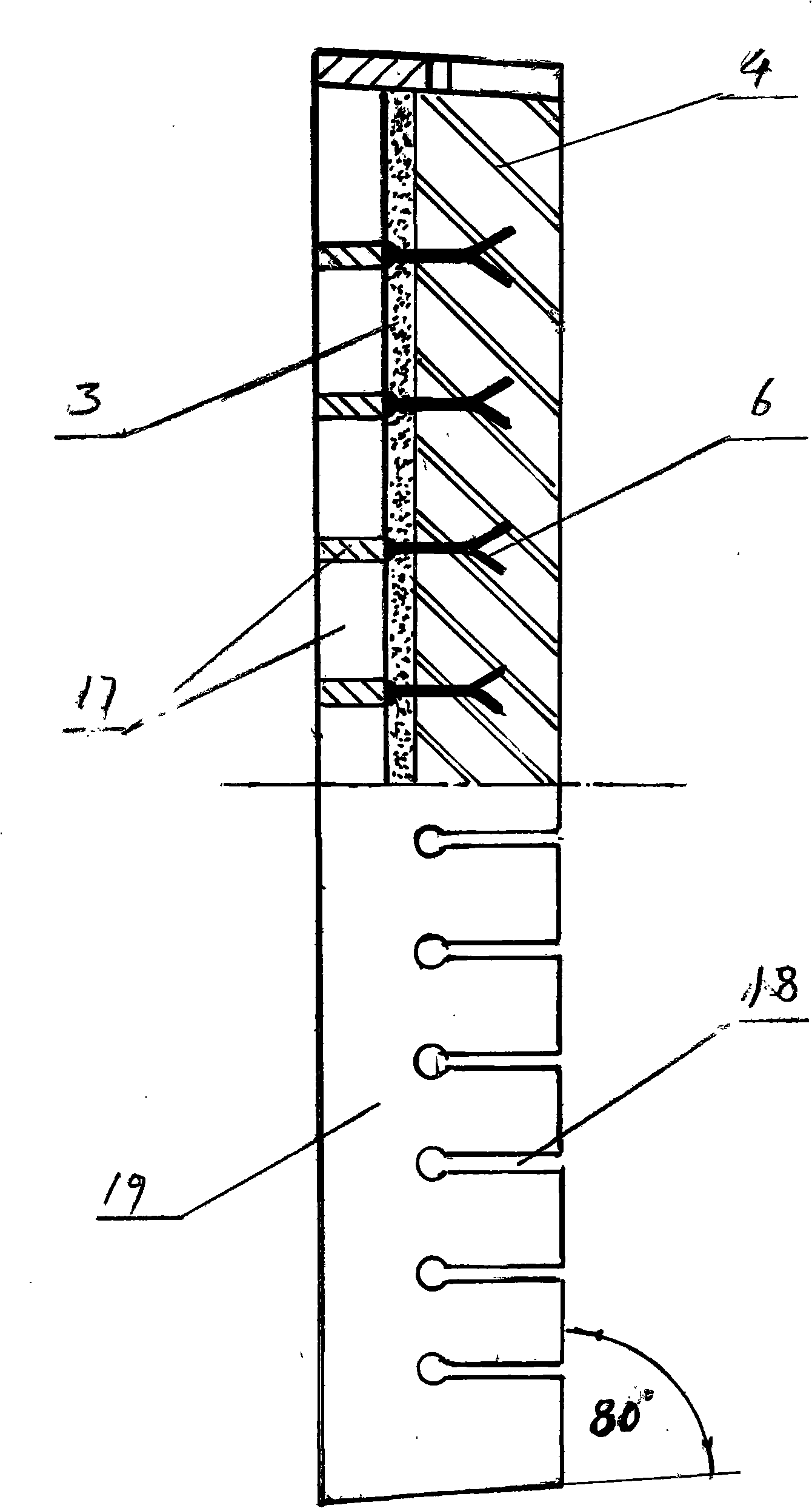
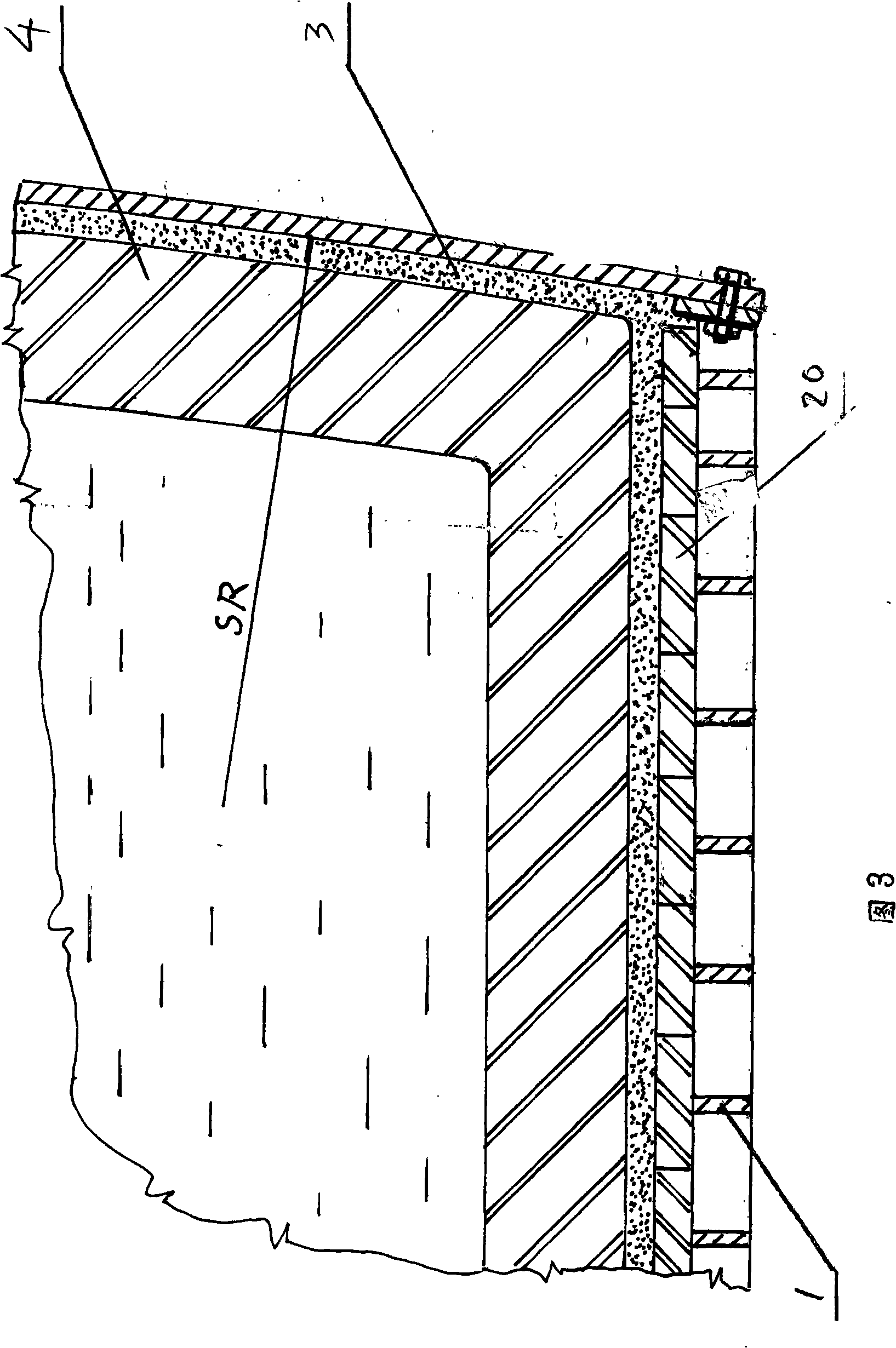
[0024] As shown in the figure, an iron mixing device is composed of an iron mixing furnace, an iron mixing tundish 7 and a tank car 10. The track 11 of the tank car 10 is arranged on the upper part of the track platform 16, and the track 11 is arranged obliquely. The track 11 gradually rises outward from the furnace body, the launder 9 of the iron mixing tundish 7 is parallel to the track 11, the cross-sectional size of the launder 9 matches the size of the iron mixing port of the iron mixing furnace, and the traction chain of the tank car 10 The tail portion of the tank car 10 is provided with a counterweight 14 equivalent in quality to the tank car 10, and the traction sprocket 8 of the tank car 10 is a forward and reverse sprocket wheel. The front portion of the track 11 is provided with a boss 13, the boss 13 has a transition section with the track at its rear, and the front end of the boss is provided with a front wheel spacer pit, and the starting point 12 of the transiti...


PUM


Abstract

The invention discloses an auxiliary device for metallurgy and steelmaking, in particular to a metal mixing device, comprising a metal mixer, a metal charging relay tank and a tank vehicle, wherein the track of the tank vehicle is installed on the upper part of a track platform; the track is inclined and rises gradually from the furnace to the outside; the chute of the metal charging relay tank is parallel to the track; the size of the cross section of the chute matches with that of the metal charging port in the metal mixer; the tail of a driving chain of the tank vehicle is equipped with a balance weight with the mass equal to that of the tank vehicle; and a driving chain wheel of the tank vehicle is a reversible chain wheel. The invention is a metal mixing device with small metal charging port and high water evaporating speed, and is capable of casting furnace brick lining and saving baker energy.

Description

technical field [0001] The invention relates to an auxiliary device for metallurgical steelmaking, in particular to an iron mixing device. Background technique [0002] At present, the mixed iron furnace shell in the prior art is generally a fully enclosed garden barrel shaped horizontally. There is an iron mixing port in the middle of the furnace roof or at the end of the side for mixing molten iron. The difference between the two is that the side mixing Adding molten iron saves energy than adding molten iron at the top. However, the current side mixing iron equipment in the prior art is not suitable for the use of side mixing molten iron in small iron mixing furnaces. The reason is that the iron mixing launders of the current existing iron mixing equipment are generally suitable for horizontal movement into or out of the iron mixing port, and its disadvantages The size of the space of the ironing hole is equal to the volume of the launder plus the increased space of the i...

Claims


Application Information

Patent Timeline
IPC IPC(8): C21C1/06
Inventor 边仁杰于树金
Owner HEBEI WENFENG STEEL & IRON
Learn More