Transmission method, transmission system, sending device and receiving device
A technology of a receiving device and a transmitting device, which is applied in the directions of transmission systems, digital transmission systems, modulated carrier systems, etc., can solve problems such as unpublished solutions and difficult application.
- Summary
- Abstract
- Description
- Claims
- Application Information
AI Technical Summary
Problems solved by technology
Method used
Image
Examples
Embodiment approach 1
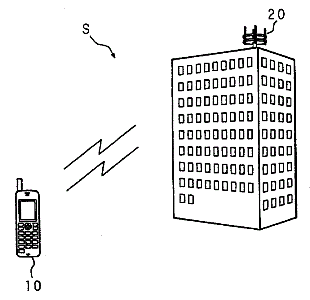
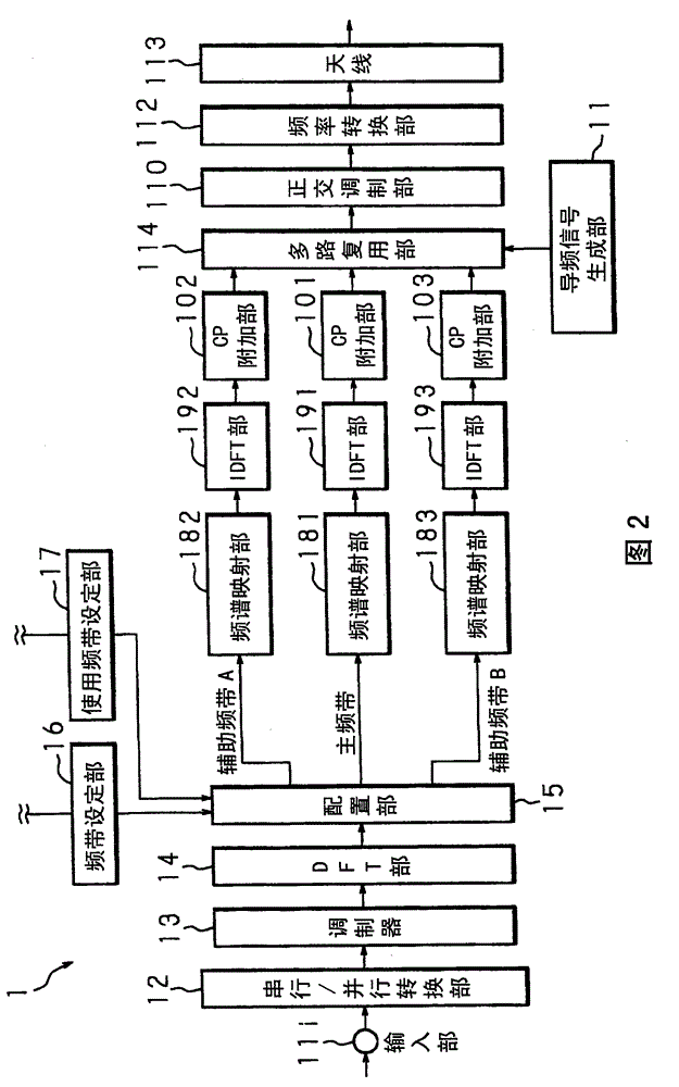
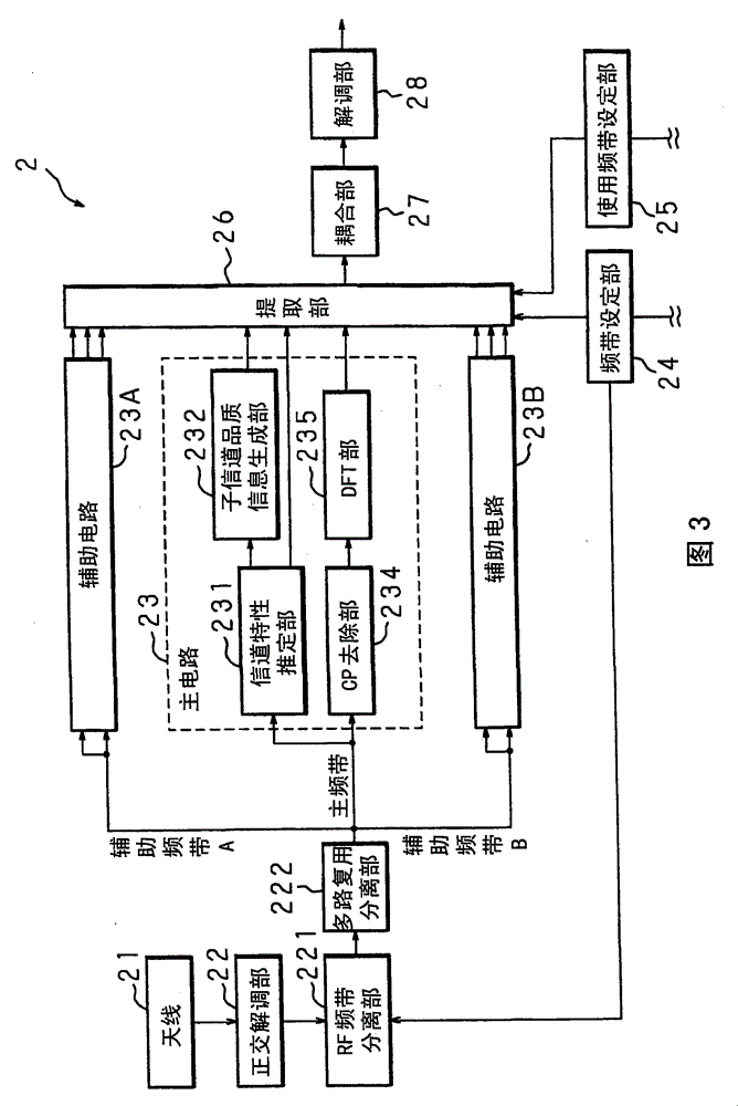
[0056] Embodiments of the present invention will be described below with reference to the drawings. figure 1It is an explanatory diagram showing the outline of the transmission system. S in the figure is a transmission system, which is configured including a mobile phone 10 as one communication device including a transmission device and a reception device, and a base station 20 as another communication device. The user of the mobile phone 10 can communicate with the mobile phone 10 of another user by sending and receiving information with the base station 20 . Next, a method (uplink) for transmitting a digital signal from the transmitting device of the mobile phone 10 to the receiving device of the base station 20 will be described, but it can also be applied to the method of transmitting a digital signal from the transmitting device of the base station 20 to the receiving device of the mobile phone 10. (downlink). Furthermore, in this embodiment, a mode in which the transmi...
Embodiment approach 2
[0085] Embodiment 2 relates to a method of distributing spectrum allocation based on allocation information of prescribed rules. Figure 10 It is a block diagram showing the hardware configuration of the transmission device 1 according to the second embodiment. Figure 11 It is a block diagram showing the hardware configuration of the receiving device 2 according to the second embodiment. In addition to the configuration of the first embodiment, the transmitting device 1 further includes an arrangement information setting unit 151 connected to the arrangement unit 15 . Furthermore, in addition to the configuration of the first embodiment, the receiving device 2 further includes a configuration information setting unit 271 connected to the coupling unit 27 . The configuration information setting unit 151 in the transmission device 1 stores the configuration information in an internal memory (not shown). This allocation information is information related to predetermined rules...
Embodiment approach 3
[0092] Embodiments 1 and 2 described the method of using the main frequency band and the auxiliary frequency band, but Embodiment 3 relates to the method of using the use frequency band within the main frequency band. Figure 13 It is a block diagram showing the hardware configuration of the transmission device 1 according to the third embodiment. in addition, Figure 14 It is a block diagram showing the hardware configuration of the receiving device 2 according to the third embodiment.
[0093] Since transmission device 1 according to Embodiment 3 uses only the main frequency band, spectrum mapping unit 181 , IDFT unit 191 , and CP adding unit 101 relating to the main frequency band are provided between arrangement unit 15 and multiplexing unit 114 . The arranging unit 15 disperses and arranges the frequency spectrum in the use frequency band within the main frequency band divided in advance by the frequency band setting unit 16 . The used frequency band setting unit 25 of ...
PUM
 Abstract
Description
Claims
Application Information
 - R&D
- Intellectual Property
- Life Sciences
- Materials
- Tech Scout
- Unparalleled Data Quality
- Higher Quality Content
- 60% Fewer Hallucinations
Browse by: Latest US Patents, China's latest patents, Technical Efficacy Thesaurus, Application Domain, Technology Topic, Popular Technical Reports.
© 2025 PatSnap. All rights reserved.Legal|Privacy policy|Modern Slavery Act Transparency Statement|Sitemap|About US| Contact US: help@patsnap.com


