Converter with reduced harmonic waves
A converter and filter technology, applied in the field of converters, can solve the problems of weak filter attenuation and filter loss increase
- Summary
- Abstract
- Description
- Claims
- Application Information
AI Technical Summary
Problems solved by technology
Method used
Image
Examples
Embodiment Construction
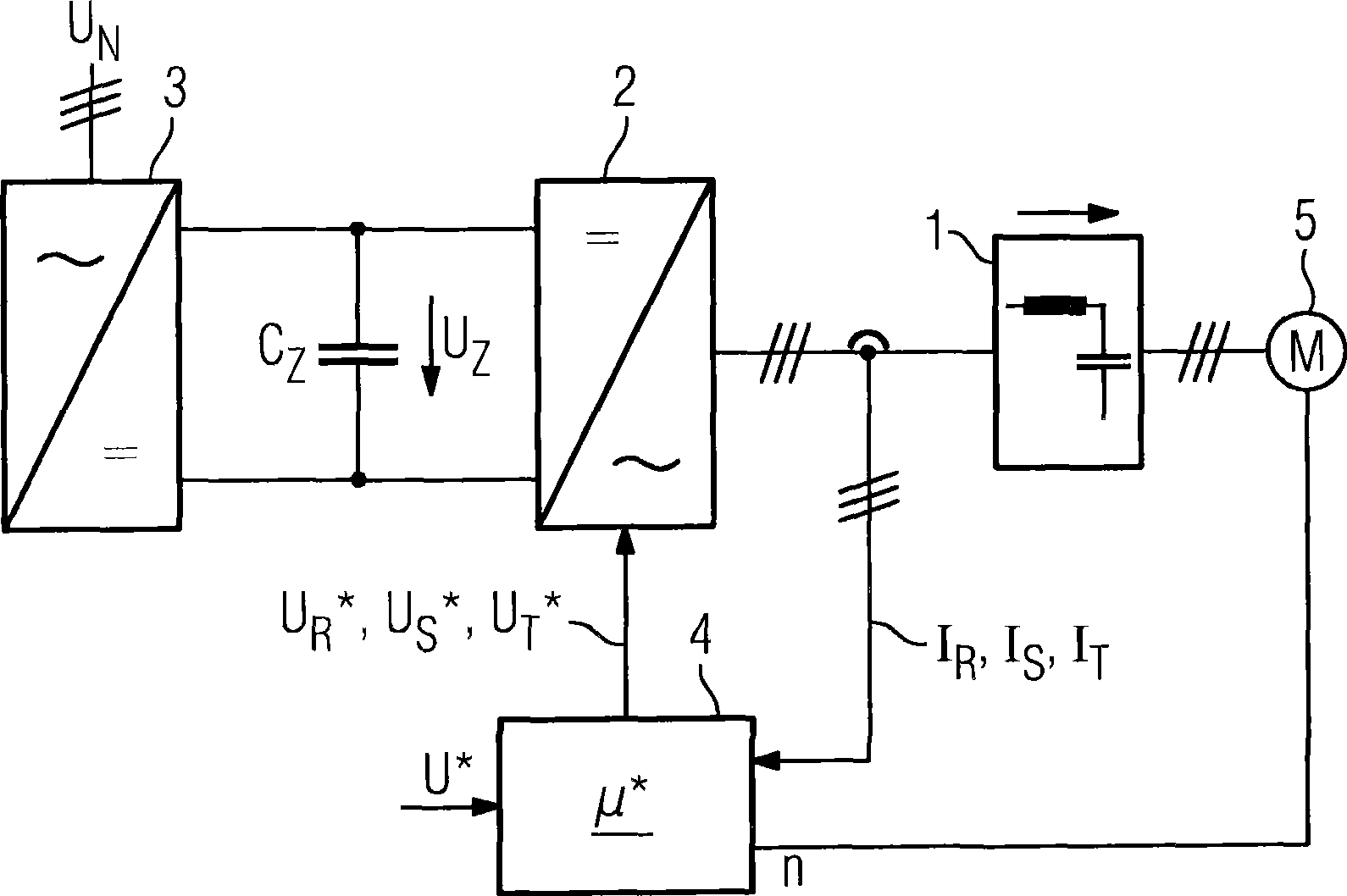
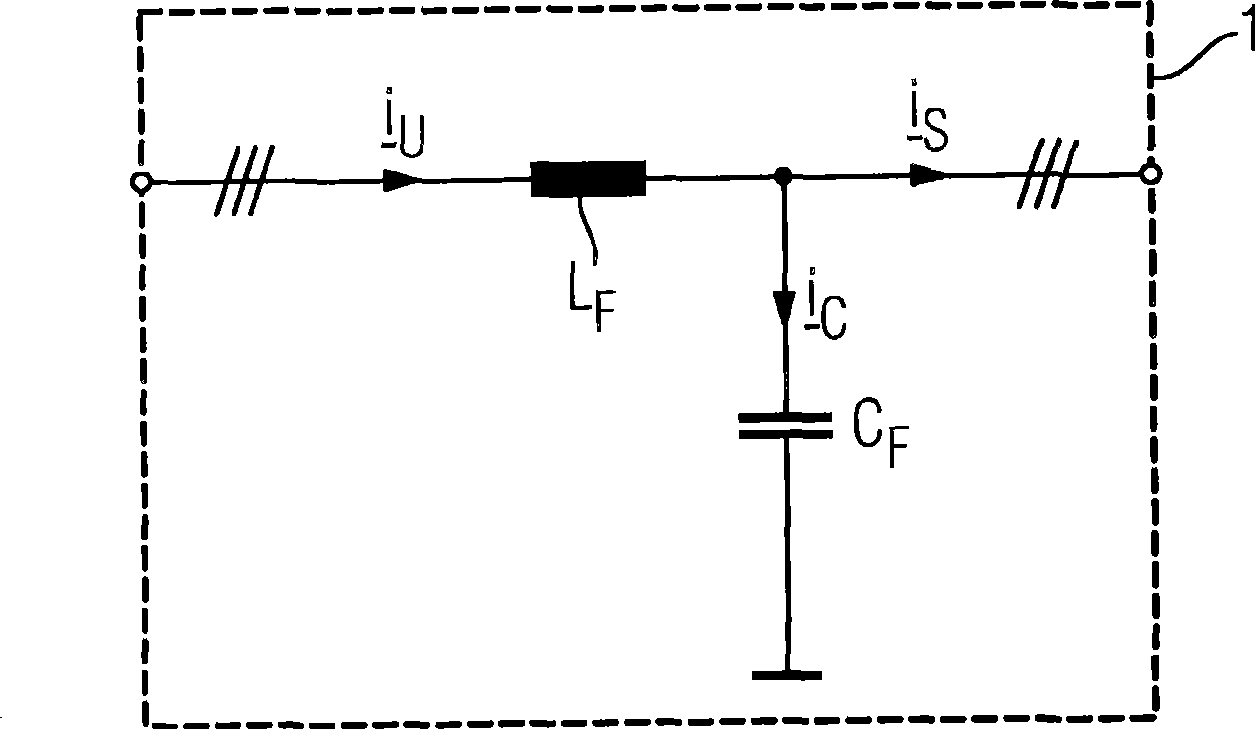
[0039] figure 1 Shown is a schematic diagram of a converter. The converter is connected at a grid voltage of U N on the grid. The converter has a rectifier 3 connected to a grid, the rectifier 3 is connected to the AC voltage U of the grid N are rectified and delivered to an intermediate circuit voltage U Z on the intermediate circuit. Intermediate circuit voltage U Z by a capacitor C Z to filter. The intermediate circuit is also connected to a three-phase inverter 2, which uses the intermediate circuit voltage U Z Generates motor voltage. The inverter is connected to the electric motor 5 via a filter 1 .
[0040] In addition, an analog and / or digital control unit 4 is provided, which controls the inverter 2 to generate an effective AC voltage U for the electric motor R * , U S * and U T * . except a control signal U * In addition, the control unit 4 can also measure the signal (such as speed n or effective AC current I R , I S or I T ) for processing. In ...
PUM
 Abstract
Description
Claims
Application Information
 - R&D
- Intellectual Property
- Life Sciences
- Materials
- Tech Scout
- Unparalleled Data Quality
- Higher Quality Content
- 60% Fewer Hallucinations
Browse by: Latest US Patents, China's latest patents, Technical Efficacy Thesaurus, Application Domain, Technology Topic, Popular Technical Reports.
© 2025 PatSnap. All rights reserved.Legal|Privacy policy|Modern Slavery Act Transparency Statement|Sitemap|About US| Contact US: help@patsnap.com


