Multi-business zone electronic fee-charging roadway system and fee charging method thereof
An electronic toll collection and transaction area technology, which is applied to antenna supports/installation devices, instruments, ticketing equipment, etc., can solve the problems of hindering the promotion of ETC lanes, low vehicle speed, and high site requirements for toll plazas, so as to reduce civil engineering renovation projects. The effect of small amount of civil engineering renovation works and large amount of civil engineering renovation works
- Summary
- Abstract
- Description
- Claims
- Application Information
AI Technical Summary
Problems solved by technology
Method used
Image
Examples
Embodiment 1
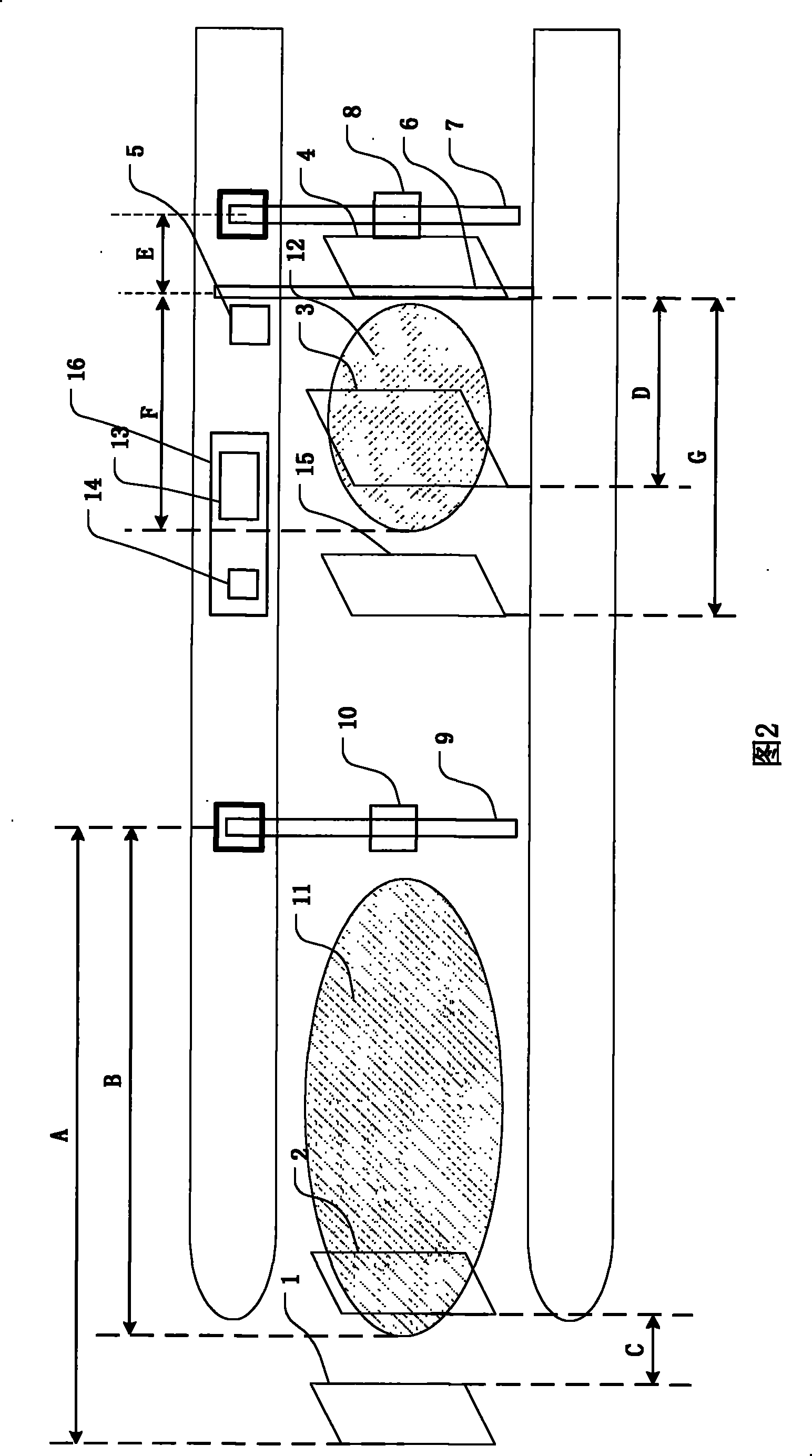
[0038] A schematic diagram of a layout of the electronic toll lane system with multiple transaction areas is shown in Figure 2. This example is an embodiment of a multi-transaction area hybrid toll lane system, including a main control computer 13, a front antenna 10, a rear antenna 8, an automatic railing 6, and vehicle detection sensors (1, 2, 3, 4, 15) , a fee display 5, a manual assisted card swiping device 14. The front antenna 10, the rear antenna 8, the automatic railing 6, the vehicle detection sensors (1, 2, 3, 4, 15), the fee display 5, and the manual auxiliary card swiping device 14 are respectively connected to the main control computer 13. The front antenna and the rear antenna cover different areas and are independent of each other; under the control of the lane system, the communication coverage area is switched according to the position of the vehicle and the transaction status, and normal transaction vehicles are released or illegal vehicles are blocked. Vehi...
Embodiment 2
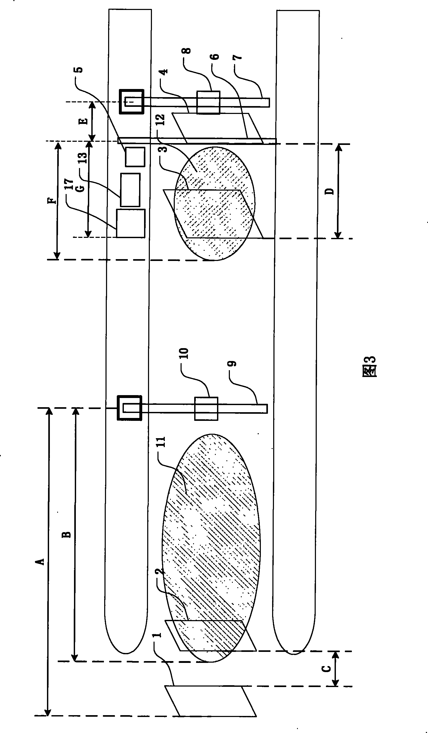
[0040] A schematic diagram of a layout of the electronic toll lane system with multiple transaction areas is shown in Figure 3. This example is an embodiment of a multi-transaction area hybrid toll lane system, including a main control computer 13, a front antenna 10, a rear antenna 8, an automatic railing 6, vehicle detection sensors (1, 2, 3, 4), a toll Amount display 5, self-service card swiping equipment 17. The front antenna 10 , the rear antenna 8 , the automatic railing 6 , the vehicle detection sensors ( 1 , 2 , 3 , 4 ), the fee display 5 , and the self-service card swiping device 17 are respectively connected to the main control computer 13 . It is characterized in that: the front antenna and the rear antenna cover different areas respectively and are independent of each other; under the control of the lane system, the communication coverage area is switched according to the position of the vehicle and the transaction status, and the normal transaction vehicles are re...
Embodiment 3
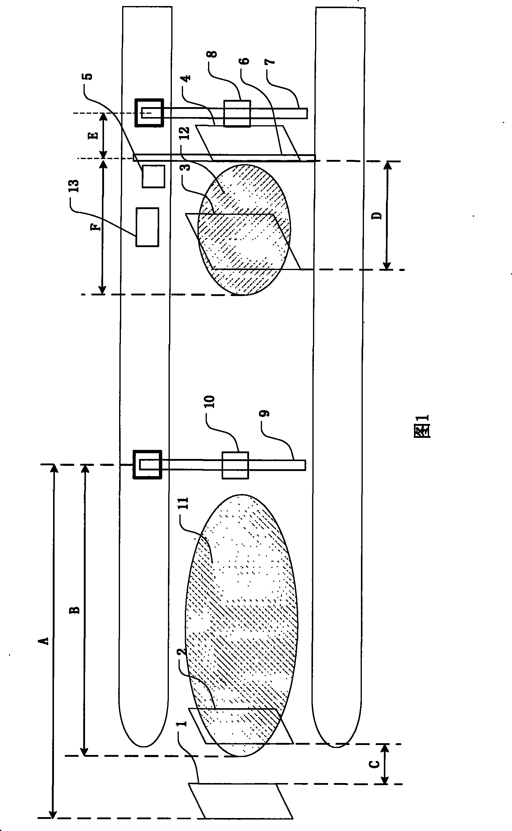
[0042] A schematic diagram of a layout of an electronic toll lane system with multiple transaction areas is shown in Figure 1. This example is an embodiment of an electronic non-stop toll lane system with multiple transaction areas, including a main control computer 13, a front antenna 10, a rear antenna 8, an automatic railing 6, vehicle detection sensors (1, 2, 3, 4), Fee display 5. The front antenna 10 , the rear antenna 8 , the automatic railing 6 , the vehicle detection sensors ( 1 , 2 , 3 , 4 ), and the fee display 5 are respectively connected to the main control computer 13 . It is characterized in that: the front antenna and the rear antenna respectively cover different areas and are independent of each other. The automatic railing 6 is located at the rear of the toll island. The front antenna 10 and the rear antenna 8 are installed on the mounting brackets 7 and 9 and are located above the lane; the mounting bracket 9 is located at the front of the toll island, the ...
PUM
 Abstract
Description
Claims
Application Information
 - R&D
- Intellectual Property
- Life Sciences
- Materials
- Tech Scout
- Unparalleled Data Quality
- Higher Quality Content
- 60% Fewer Hallucinations
Browse by: Latest US Patents, China's latest patents, Technical Efficacy Thesaurus, Application Domain, Technology Topic, Popular Technical Reports.
© 2025 PatSnap. All rights reserved.Legal|Privacy policy|Modern Slavery Act Transparency Statement|Sitemap|About US| Contact US: help@patsnap.com


