Layout structure of source driver and method thereof

A technology of source driver and wiring structure, which is applied in the direction of instruments, nonlinear optics, static indicators, etc., and can solve problems such as crosstalk and band unevenness

Inactive Publication Date: 2009-08-19
HIMAX TECH LTD
View PDF0 Cites 8 Cited by
  • Summary
  • Abstract
  • Description
  • Claims
  • Application Information

AI Technical Summary

Problems solved by technology

Therefore, the present invention can solve the problems of banding unevenness and crosstalk on the display panel to obtain optimal visual quality

Method used


Image

  • Layout structure of source driver and method thereof
  • Layout structure of source driver and method thereof
  • Layout structure of source driver and method thereof

Examples


Embodiment Construction

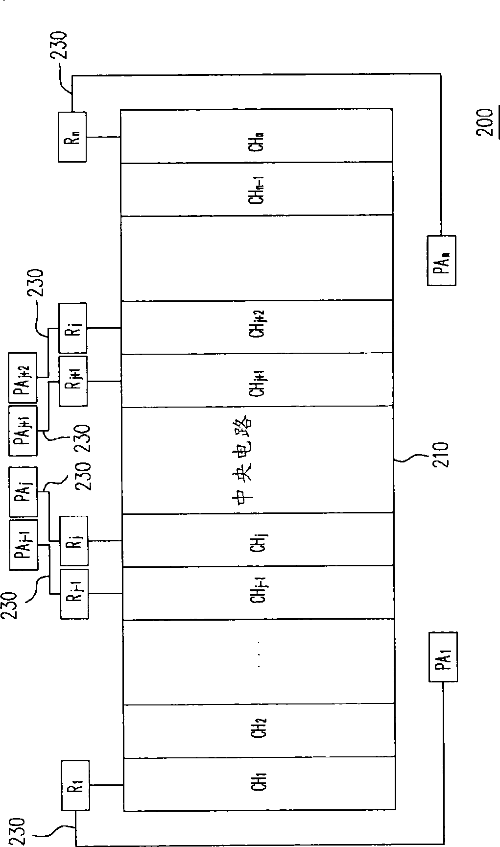
[0037] figure 2 It is a wiring structure of a source driver according to an embodiment of the present invention. Please refer to figure 2 , the source driver 200 has a plurality of driving channels CH1˜CHn, wherein n is the number of driving channels. Through the driving channels CH1 ˜CHn of the source driver 200 , data driving signals can be transmitted to the pixel units on the data lines. The wiring structure of the source driver 200 includes a central circuit 210 , a plurality of pads PA1 ˜ PAn and a plurality of winding wires 230 , wherein the winding wires 230 respectively include a plurality of resistance units R1 ˜ Rn. The central circuit 210 processes the data driving signal to control data transmission. The pads PA1˜PAn are used to electrically connect the source driver 200 to an external circuit, such as a pixel unit (not shown in FIG. figure 2 ). The winding wires 230 are respectively coupled between the driving channels CH1 ˜CHn and the pads PA1 ˜PAn. The...


PUM


Abstract

A layout structure of a source driver having a plurality of driving channels, and a method thereof are provided herein. The layout structure of the source driver includes a plurality of pads and a plurality of routings. The pads are used for making electric contact between the source driver and an external circuit. The routings are respectively coupled between the driving channels and the pads for transmitting the signal. Besides, the routings respectively includes a plurality of resistance units, and each of the resistance units is used for adjusting the resistance of the respective routing so as to minimize a variation of the driving ability between the pads.

Description

technical field [0001] The invention relates to a wiring structure of a source driver and a method thereof, and in particular utilizes wiring technology to minimize the difference in driving capability between pads in the source driver. Background technique [0002] In recent years, a liquid crystal display (LCD) has become a mainstream in the market due to its advantages of low power loss, zero radiation, and high space utilization. The source driver is an important component in the liquid crystal display, which converts digital data signals into analog signals for displaying images, and outputs the analog signals to each pixel on the display panel. [0003] Figure 1A It is a block diagram of the wiring structure of a conventional source driver. Please refer to Figure 1A , the wiring structure of the source driver 100 includes a central circuit 110, a plurality of driving channels C1-Cn and a plurality of pads P1-Pn. With the remarkable progress of optoelectronic techno...

Claims


Application Information

Patent Timeline
Patent Type & Authority Applications(China)
IPC IPC(8): G02F1/133G09G3/36
CPCG02F1/133371G02F2001/134372G02F1/134363G02F1/134372Y10T29/49002
Inventor 张智兴
Owner HIMAX TECH LTD
Why Eureka
Try Eureka