Dynamic target modulation transfer function measurement method
A technique of modulating transfer function and dynamic target, which is applied in the direction of testing optical performance, etc., and can solve the problems of not taking into account the influence of lens transfer function measurement results, not taking into account noise, not taking into account, etc.
- Summary
- Abstract
- Description
- Claims
- Application Information
AI Technical Summary
Problems solved by technology
Method used
Image
Examples
example 1
[0064] The method for measuring the dynamic target modulation transfer function of the present invention has the following steps:
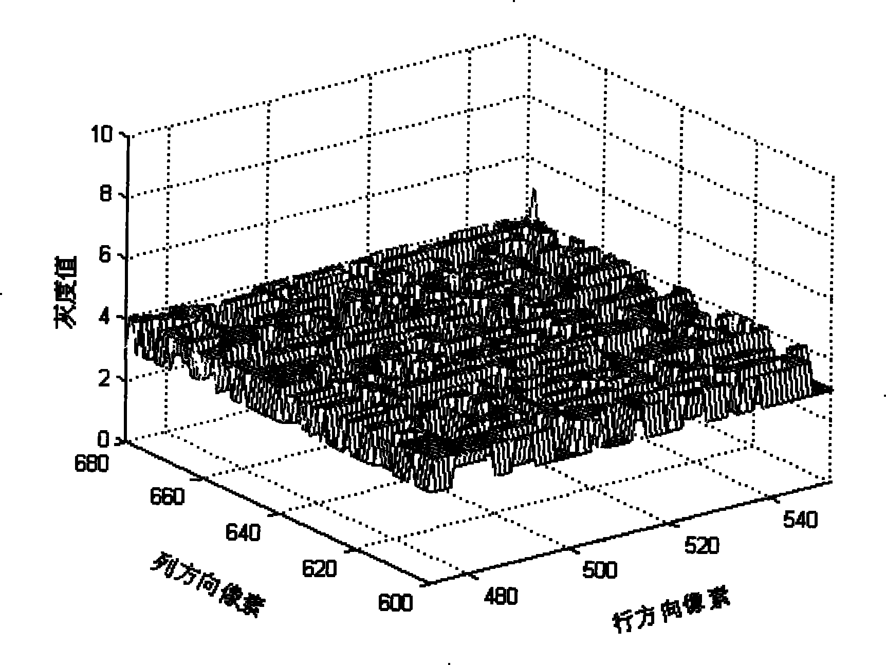
[0065] a. Under the condition of turning off the point light source 1, the image sensor 3 forms an image, and the recorded synthetic interference image of the dark current of the image sensor and the background image is shown in Figure 2. It can be seen that the dark current of the image sensor and the background image make the synthetic interference image Noise with a grayscale value of 3 or 4.
[0066] b. On the basis of step a, without changing any conditions except the point light source 1, light the point light source 1 and keep it still relative to the measurement system, the image sensor 3 is imaged, and the recorded dark current of the image sensor, The composite still image of the background image and the static target is shown in Figure 3. Figure 4 is the local feature map of Figure 3, from which it can be seen that the noise gray value...
example 2
[0085] The corresponding measuring device and the parameters of the device in this embodiment are completely consistent with embodiment 1, and the first a, b, c, d, e steps of the measuring method are also completely consistent with embodiment 1, and the f, g, h, The i-step method is as follows:
[0086] f. Correct the de-interference static image obtained in step d, eliminate the residual information randomly introduced into the de-interference static image by background light and image sensor dark current, and obtain the secondary corrected static image as shown in Figure 18 and Figure 19 is the local feature map in Figure 18, from which it can be seen that this step has corrected the noise gray value in the de-interference static image to 0.
[0087] g. Correct the de-interference dynamic image obtained in step e, and eliminate the residual information randomly introduced into the de-interference dynamic image by the background light and the dark current of the image sensor...
PUM
 Abstract
Description
Claims
Application Information
 - R&D
- Intellectual Property
- Life Sciences
- Materials
- Tech Scout
- Unparalleled Data Quality
- Higher Quality Content
- 60% Fewer Hallucinations
Browse by: Latest US Patents, China's latest patents, Technical Efficacy Thesaurus, Application Domain, Technology Topic, Popular Technical Reports.
© 2025 PatSnap. All rights reserved.Legal|Privacy policy|Modern Slavery Act Transparency Statement|Sitemap|About US| Contact US: help@patsnap.com


