


Quick Research
Generate reliable direction feasibility study reports for your R&D in just a few steps.

Technical Q&A
Discover and master advanced knowledge NOW. Basics, ideas, possibilities, all at once.

Find Solutions
As an expert in R&D theories, this can generate solutions to your technical problems instantly.

Evaluate Feasibility
Analyze your overall solution with one click, know your potential R&D risks in advance.

Monitor Landscape
Get weekly tech updates, stay abreast of the latest tech innovations and key insights.
Sintered power generation by waste heat system with by-product gas afterburning
A technology of by-product gas and waste heat power generation, which is applied in waste heat treatment, machine/engine, lighting and heating equipment, etc., can solve the problems of not increasing the exhaust gas temperature as much as possible, low superheated steam parameters, and low thermal efficiency of the system, so as to increase supplementary combustion The effect of flue gas volume, increasing steam parameters and increasing flue gas temperature
- Summary
- Abstract
- Description
- Claims
- Application Information
AI Technical Summary
Problems solved by technology
Method used
Image

Examples
Embodiment 1
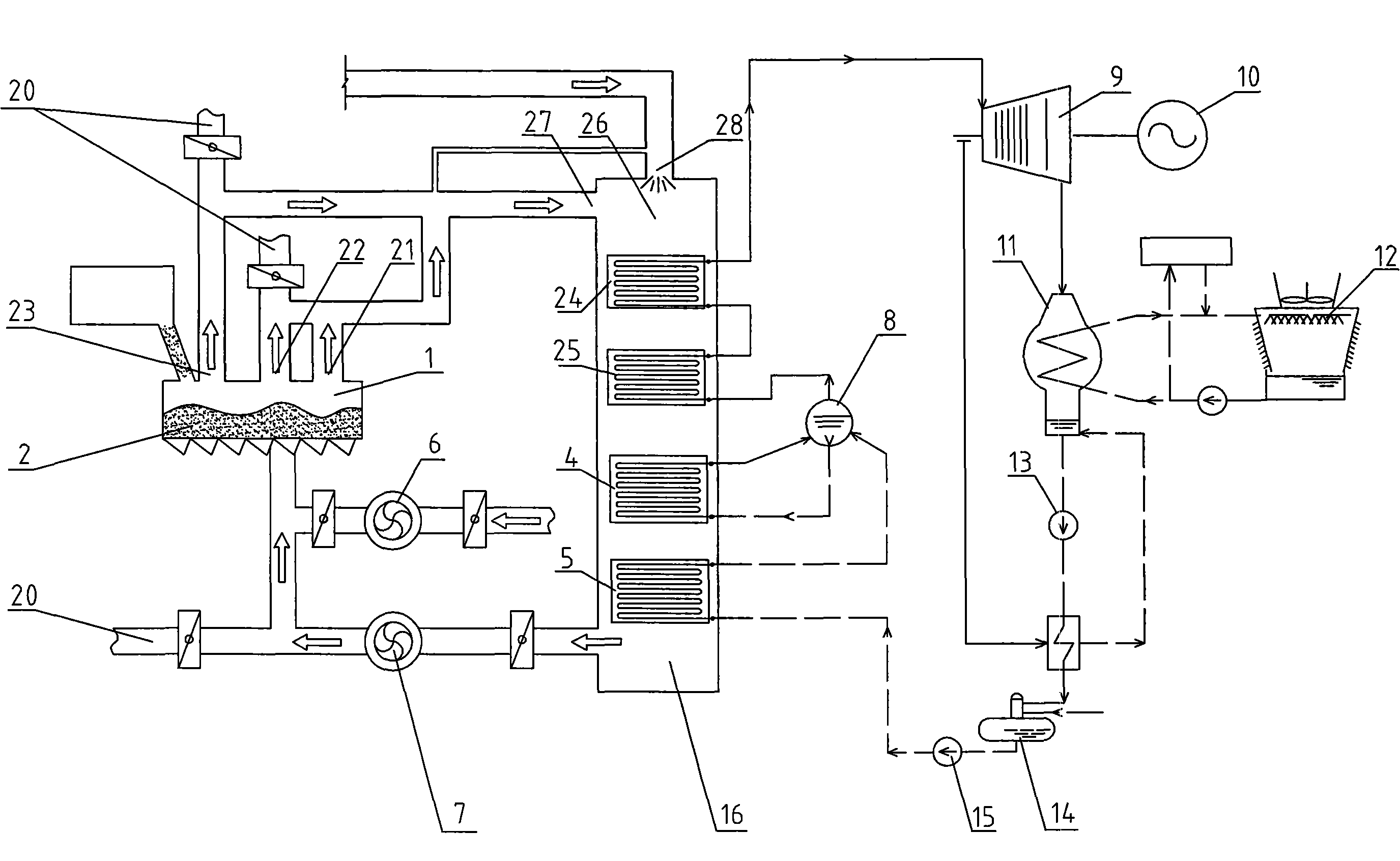
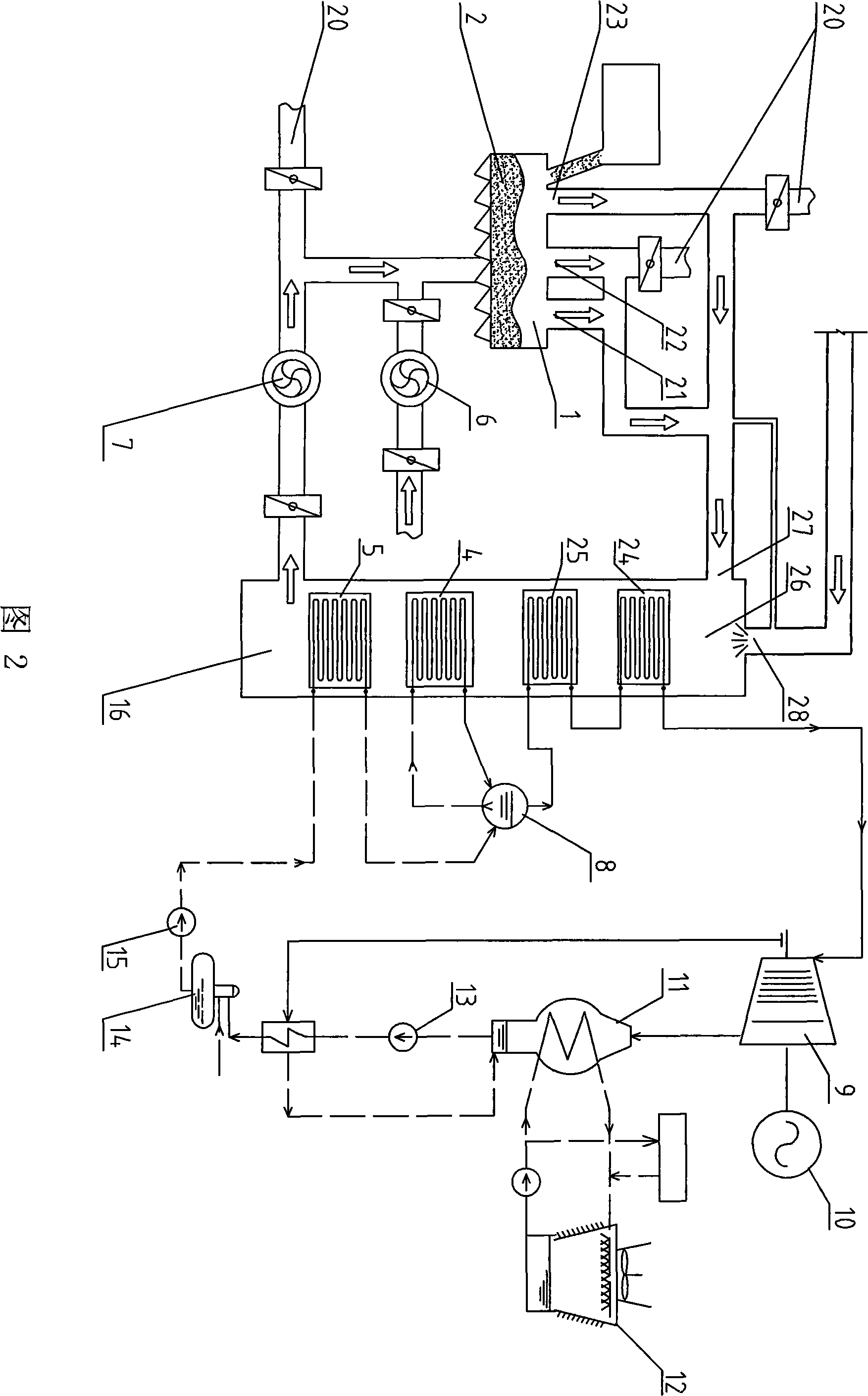
[0013] The structure of this embodiment is shown in Figure 2. The sintering waste heat power generation system with by-product gas supplementary combustion includes a cooler 1, a waste heat boiler 16, a steam drum 8, a steam turbine 9, a generator 10, a condenser 11, and a cooling tower. 12. Condensate pump 13, deaerator 14 and boiler feed water pump 15. Cooler 1 is provided with three exhaust gas outlets, which are the high-temperature exhaust gas outlet 23 located in the high-temperature zone, the medium-temperature exhaust gas outlet 22 located in the medium-temperature zone, and the exhaust gas outlet located in the low-temperature zone. Low-temperature exhaust gas outlet 21, combustion furnace 26, high-temperature superheater 24, low-temperature superheater 25, evaporator 4 and economizer 5 are arranged in the waste heat boiler 16 from top to bottom, and a combustion furnace 26 of the waste heat boiler 16 is provided with The exhaust gas inlet 27 connected to the high-temp...
Embodiment 2
[0019] The structure of this embodiment is shown in Figure 3, and the difference from Embodiment 1 is that a combustion furnace 26, a high-pressure superheater 29, a high-pressure evaporator 30, a high-temperature economizer 31, Low-pressure superheater 32, low-pressure evaporator 33 and low-temperature economizer 34, steam drum is divided into high-pressure steam drum 35 and low-pressure steam drum 36, boiler feed water pump 15 is connected with the inlet of low-temperature economizer 34, low-temperature economizer 34 The outlet is connected to the inlet of the high-temperature economizer 31 and the water inlet of the low-pressure steam drum 36, the water inlet of the low-pressure evaporator 33 is connected to the water outlet of the low-pressure steam drum 36, and the outlet of the low-pressure evaporator 33 is connected to the vapor-liquid of the low-pressure steam drum 36. The two-phase inlets are connected, the steam inlet of the low-pressure superheater 32 is connected wi...
PUM
 Abstract
Description
Claims
Application Information
 - R&D Engineer
- R&D Manager
- IP Professional
- Industry Leading Data Capabilities
- Powerful AI technology
- Patent DNA Extraction
Browse by: Latest US Patents, China's latest patents, Technical Efficacy Thesaurus, Application Domain, Technology Topic, Popular Technical Reports.
© 2024 PatSnap. All rights reserved.Legal|Privacy policy|Modern Slavery Act Transparency Statement|Sitemap|About US| Contact US: help@patsnap.com