


Quick Research
Generate reliable direction feasibility study reports for your R&D in just a few steps.

Technical Q&A
Discover and master advanced knowledge NOW. Basics, ideas, possibilities, all at once.

Find Solutions
As an expert in R&D theories, this can generate solutions to your technical problems instantly.

Evaluate Feasibility
Analyze your overall solution with one click, know your potential R&D risks in advance.

Monitor Landscape
Get weekly tech updates, stay abreast of the latest tech innovations and key insights.
Ultrasonic diagnostic apparatus
A diagnostic device, ultrasonic technology, applied in the direction of acoustic wave diagnosis, infrasonic wave diagnosis, ultrasonic/sonic wave/infrasonic wave diagnosis, etc., which can solve the problems of waste needle biopsy, retention, and inability to confirm
- Summary
- Abstract
- Description
- Claims
- Application Information
AI Technical Summary
Problems solved by technology
Method used
Image

Examples
no. 1 approach
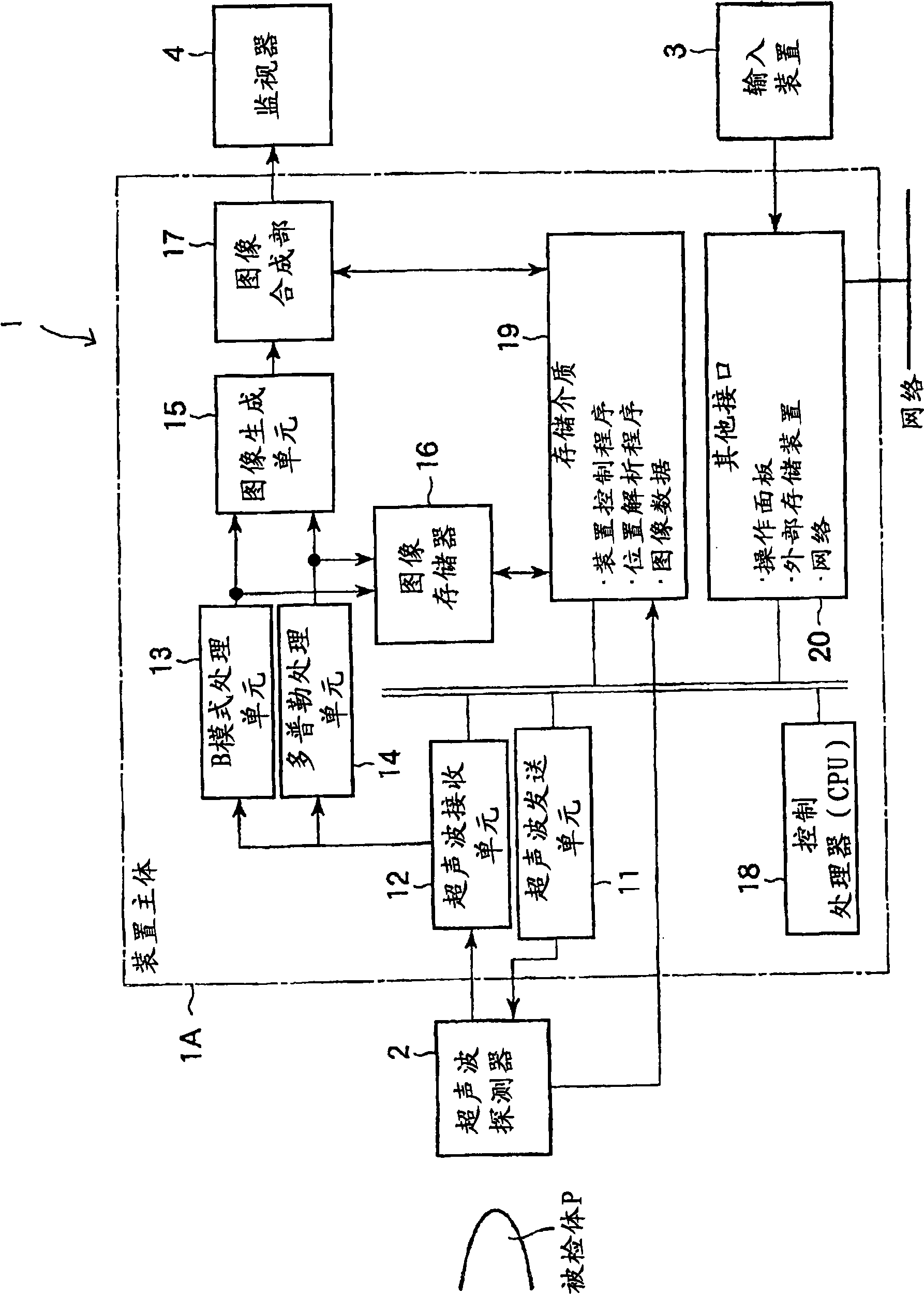
[0039] figure 1 It is a block diagram which shows the structure of the ultrasonic diagnostic apparatus 1 which concerns on one Embodiment of this invention.
[0040] The ultrasonic diagnostic apparatus 1 includes an apparatus main body 1A, a probe 2 as an ultrasonic contactor, an input device 3, and a monitor 4 as a display device.
[0041] In the apparatus main body 1A, an ultrasonic transmitting unit 11, an ultrasonic receiving unit 12, a B-mode processing unit 13, a Doppler processing unit 14, an image generating unit 15 as an image generating device, an image memory 16, an image synthesizing unit 17, A control processor (CPU) 18, an internal storage unit 19, an interface unit 20, and an optical sensor (not shown) are controlled.
[0042] The probe 2 described above generates ultrasonic waves according to a drive signal from the ultrasonic wave transmitting unit 11 and transmits them to the subject P. As shown in FIG. The probe 2 includes a plurality of piezoelectric vibr...
no. 2 approach
[0073] Figures 9 to 13 A second embodiment of the present invention is shown.
[0074] In addition, about the same part as the part demonstrated in the said 1st Embodiment, the same code|symbol is attached|subjected and the detailed description is abbreviate|omitted.
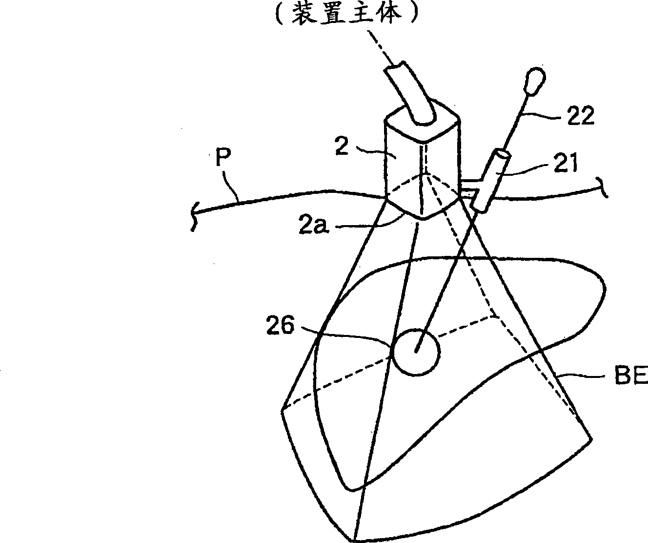
[0075] In the above-described first embodiment, the needle biopsy is performed by bringing the distal end portion of the probe 2 into contact with the surface of the subject P to scan ultrasonic waves three-dimensionally, but in the second embodiment, as Figure 9 As shown, the needle biopsy is performed by bringing the distal end portion 2a of the probe 2 into contact with the surface of the subject P to scan ultrasonic waves two-dimensionally.
[0076] Next, the case where a needle biopsy is performed by scanning ultrasonic waves two-dimensionally will be described.
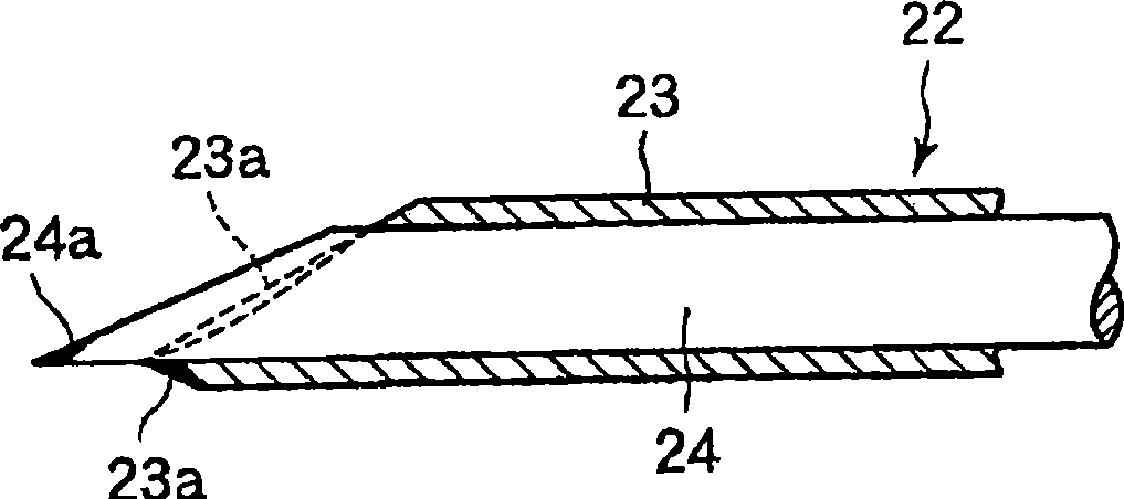
[0077] First, the puncture needle 22 is mounted in the puncture adapter 21 of the probe 2 . Next, the distal end portion 2a of the probe 2 i...
PUM
 Abstract
Description
Claims
Application Information
 - R&D Engineer
- R&D Manager
- IP Professional
- Industry Leading Data Capabilities
- Powerful AI technology
- Patent DNA Extraction
Browse by: Latest US Patents, China's latest patents, Technical Efficacy Thesaurus, Application Domain, Technology Topic, Popular Technical Reports.
© 2024 PatSnap. All rights reserved.Legal|Privacy policy|Modern Slavery Act Transparency Statement|Sitemap|About US| Contact US: help@patsnap.com