
Method and apparatus for converting marine wave energy by means of a difference in flow resistance form factors into electricity

一种波形因数、波浪的技术,应用在海洋能发电、减少船只运动的设备、船只增加稳定性的设备等方向,能够解决能源不稳定、昂贵、能量回收和储备困难等问题

Inactive Publication Date: 2009-08-12
赛波·瑞纳内恩 +1
View PDF5 Cites 10 Cited by
  • Summary
  • Abstract
  • Description
  • Claims
  • Application Information

AI Technical Summary

Problems solved by technology

Due to the instability of these energy sources, energy recovery and storage has so far been very difficult and expensive

Method used


Image

  • Method and apparatus for converting marine wave energy by means of a difference in flow resistance form factors into electricity
  • Method and apparatus for converting marine wave energy by means of a difference in flow resistance form factors into electricity
  • Method and apparatus for converting marine wave energy by means of a difference in flow resistance form factors into electricity

Examples


Embodiment Construction

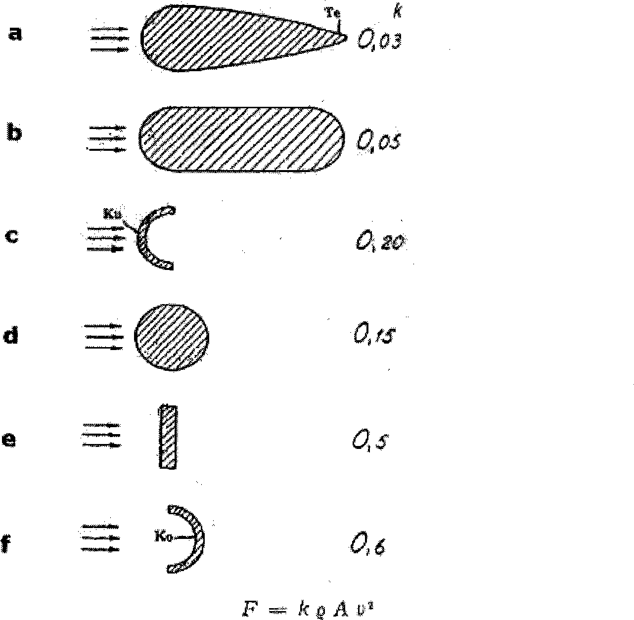
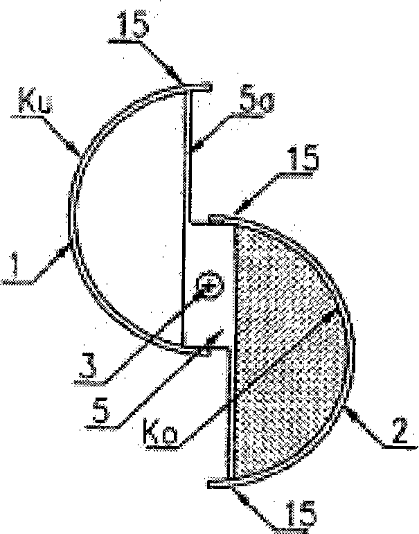
[0044] figure 1 Examples of experimental measurement results of form factor for fluid media obtained in Finland, such as the example of a...f used in some forming, a flow process from left to right indicated by the arrow in the figure . The formula for flow resistance F is given under the discontinuous figure f. In Figure c, the water flow comes to contact the convex (Ku) shape, while in Figure f with the complementary concave (Ko) shape. The only difference is that there is a 180 degree transformation in the position of the parts. Although the parts are equal according to their projected areas, due to this shape, they have 3 times the flow resistance.

[0045] When the water stream hits the same convex (Ku) shape, the flow resistance acting on the downstream water stream can be observed between parts a...d of the drawings. The form factor k shows a considerable difference due to the turbulence of the fluid that resists the tail end.

[0046] The maximum resistance to the moveme...


PUM


Abstract

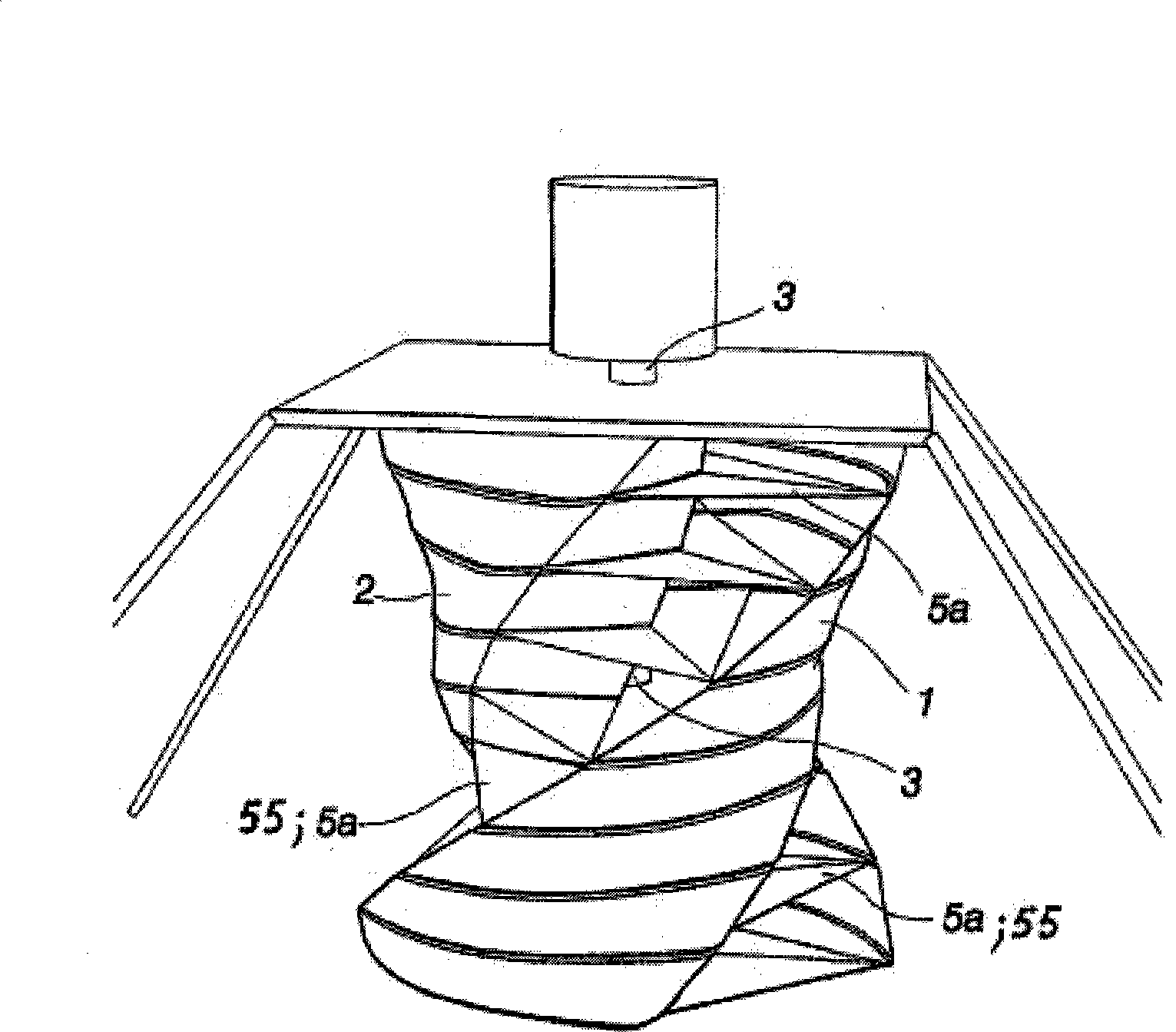
The invention relates to a method and apparatus for gradually converting marine wave energy into electricity. The energy reserve provided by wind power holds enough energy for the needs of the entire mankind. The invention provides an efficient means of putting this energy reserve to practical use. Mounted on a rotating power shaft (3) is a pair of form parts (1, 2), the convex and concave shape, especially the round-pointed open V-shape of which reverses its orientation by 180 degrees, i.e. turns from convex to concave, whenever the power shaft makes a rotation of 180 degrees. The circular motion of water occurring in a wave drives such a turbine effectively while the wave dies out. The pair of convex and concave form parts (1, 2) extends helically around the power shaft (3), whereby water currents in all directions, which come to contact with the pair of form parts, produce a rotative moment.

Description

Technical field [0001] The present invention relates to the use of flow resistance form factor to gradually convert repeated ocean wave motions into electricity through a pair of special-shaped components, which extend spirally around an axis at 180+180 degrees, and gradually flow or oscillate. Open under the action of force. [0002] In particular, the present invention relates to a method and device for regenerating the oscillating mechanical motion and centrifugal energy of liquid water molecules in a large number of ocean waves, so as to conveniently use electricity in different directions and even from different depth levels. In the form of regeneration, such as regenerating electricity from floating and rotating generator platforms in an environmentally friendly and economical manner. This method does not require huge and expensive structures or equipment, nor does it convert energy into other forms. When used, it will exist in the form of natural oscillating motion, flow, p...

Claims


Application Information

Patent Timeline
Patent Type & Authority Applications(China)
IPC IPC(8): F03B3/12F03B13/14B63B21/56
CPCY10S415/906F03B13/183Y02T70/59Y02E10/38F05B2240/213Y02E10/28B63B2035/4466F05B2250/25B63B39/00B63H19/02F05B2240/931Y02E10/30Y02T70/5236Y02E10/20
Inventor 赛波·瑞纳内恩米科·瑞纳内恩
Owner 赛波·瑞纳内恩
Learn More