
Atomizing chilling and fractional condensing process and apparatus used for biomass, coal or oil shale pyrolysis and liquefaction

A technology of graded condensation and oil shale, applied in the directions of liquefaction, refrigeration, liquefaction, solidification, etc., can solve the problems of pyrolysis steam quenching, slow cooling speed, and liquid polycondensation quality.

Inactive Publication Date: 2009-08-05
SHANDONG UNIV OF SCI & TECH
View PDF1 Cites 7 Cited by
  • Summary
  • Abstract
  • Description
  • Claims
  • Application Information

AI Technical Summary

Problems solved by technology

However, practice has proved that the cooling speed of this condensing device is slow and the condensation is not complete. In addition, there is ash in the oil, which is prone to blockage.
If the high-temperature pyrolysis steam cannot be cooled quickly below the secondary cracking reaction temperature, secondary cracking will easily occur, which will affect the yield and quality of liquid products
The spray and falling film composite condensing device mentioned in patent ZL200710162077.9 for pyrolysis and liquefaction of coal or biomass solves the problem of rapid cooling of pyrolysis steam, but because the tube-and-tube indirect heat exchanger acts as the falling film condensing section first Contact with high-temperature pyrolysis gas, the blockage problem of the device has not been completely solved; in addition, the secondary processing and utilization of the condensed liquid requires high-temperature heating and separation. First, the liquid is prone to polycondensation and quality deterioration during the heating process. Second, the entire process energy Unreasonable use, high energy consumption

Method used


Image

  • Atomizing chilling and fractional condensing process and apparatus used for biomass, coal or oil shale pyrolysis and liquefaction

Examples


Embodiment Construction

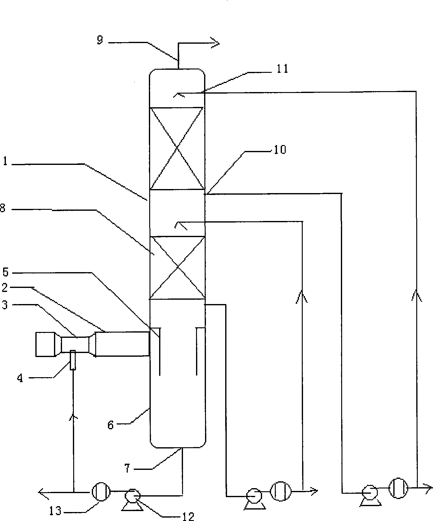
[0010] The present invention will be described in detail below in conjunction with the accompanying drawings: the spray quenching and staged condensation process and device for the pyrolysis and liquefaction of biomass, coal or oil shale described in the present invention are heavy liquid cooling backflow through the quenching oil atomization nozzle (4) From the venturi throat (3) spray into the high-temperature pyrolysis gas flowing through the Venturi type into the tower tube (2), the oil mist and the pyrolysis gas are fully contacted and quenched, so that the temperature of the oil and gas is low At 300°C, it enters the graded condensation tower (1) at high speed along the tangential direction; the oil and gas are centrifugally separated by the cyclone drum (5), and the heavy liquid flows downward into the bottom section of the tower (6) and flows out from the heavy liquid outlet (7) and Pressurized by the oil pump (12) and cooled by the heat exchanger (13), part of the liqu...


PUM


Abstract

The invention provides a spraying quenching and fractional condensation process and device for the pyrolysis and liquefaction of biomass, coal or oil shale. A heavy liquid is cooled and flows back, and then the heavy liquid is sprayed into pyrolytic gas with high temperature from the throat of a Venturi tube by a quenching oil atomized nozzle, wherein the pyrolytic gas with high temperature flows through a pyrolytic gas inlet tube in a Venturi type; the atomized oil is in full contact with the pyrolytic gas and is quenched, which lowers the temperature of the oil below 300 DEG C, and then the oil enters a tower shell at a high speed in the tangential direction; the oil and the gas are centrifugalized by a cyclone; the heavy liquid flows downwards into the bottom of the tower, and then the heavy liquid flows out from a heavy-liquid outlet and is pressurized by an oil pump and cooled by a heat exchanger; part of the heavy liquid flows back and is used as a cooling liquid while the other part of the heavy liquid is sent out to be used as a product; the oil and the gas separated by the cyclone flow upwards and successively pass through the first separation section for distillation and condensation to the forth separation section for distillation and condensation, and light liquids with different boiling ranges are obtained after the oil and the gas are condensed and separated gradually; the light liquids flow out from a light-liquid outlet and are pressurized by the oil pump and cooled by the heat exchanger; part of the light liquid flows back and is used as a cooling liquid while the other part is sent out to be used as a product; at last, noncondensable gas flows out from a gas outlet at the top of the tower shell and is used as a dry-gas product for pyrolysis.

Description

1. Technical field [0001] The invention relates to a spray quenching and graded condensation process and device for pyrolysis and liquefaction of biomass, coal or oil shale, and belongs to the field of energy and chemical industry. 2. Background technology [0002] In the pyrolysis and liquefaction process of biomass, coal or oil shale, it is generally required that the condensing system can quickly condense the high-temperature pyrolysis steam to improve the yield and quality of liquid products. The condensing system of the existing pyrolysis liquefaction equipment is mainly composed of several sets of heat exchangers connected in series, and the high-temperature pyrolysis steam is condensed through wall cooling. However, practice has proved that the cooling speed of this condensing device is slow and the condensation is not complete, and in addition, there is dust in the oil, which is prone to blockage. If the high-temperature pyrolysis steam cannot be cooled quickly belo...

Claims


Application Information

Patent Timeline
IPC IPC(8): F25J3/02
Inventor 田原宇乔英云盖希坤梁鹏
Owner SHANDONG UNIV OF SCI & TECH
Learn More