Controllable liquid injection pipe and controllable liquid injection method convenient for downhole and uplifting

A liquid injection pipe and liquid injection technology, which is applied in the direction of earthwork drilling, wellbore/well components, and production fluids, etc., can solve the problems of reducing the lifting speed, increasing the outer diameter of the bladder, and low discharge speed, so as to increase the lifting speed , Eliminate the effect of skin damage

Inactive Publication Date: 2012-12-26
ANTON BAILIN OILFIELD TECH (BEIJING) CO LTD
View PDF0 Cites 0 Cited by
  • Summary
  • Abstract
  • Description
  • Claims
  • Application Information

AI Technical Summary

Problems solved by technology

Due to the small annular gap between the injection pipe and the well wall, the inflated bladder packer severely affected the lifting of the injection pipe
On the one hand, during the lifting process of the injection pipe, the inflated bladder packer caused damage to the bladder due to friction with the well wall; A serious accident occurred due to the inability to lift up the well
[0008] The condition that the bladder packer does not expand is that the difference between the inner and outer liquid levels of the liquid injection pipe does not exceed 50 meters. Because the discharge velocity of the throttling device is very low, in order to ensure the balance of the internal and external pressures of the liquid injection pipe during lifting, the bladder packer The spacer can be in a contracted state, so the lifting speed can only be reduced, and a little injection medium is leaked through the throttling device, and then the liquid injection pipe is lifted a little, which is far from meeting the normal production needs of oil wells, gas wells or injection wells

Method used


Image

  • Controllable liquid injection pipe and controllable liquid injection method convenient for downhole and uplifting
  • Controllable liquid injection pipe and controllable liquid injection method convenient for downhole and uplifting
  • Controllable liquid injection pipe and controllable liquid injection method convenient for downhole and uplifting

Examples


Embodiment 1

[0036] Embodiment 1 Controllable Liquid Injection Pipe Structure

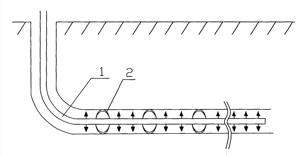
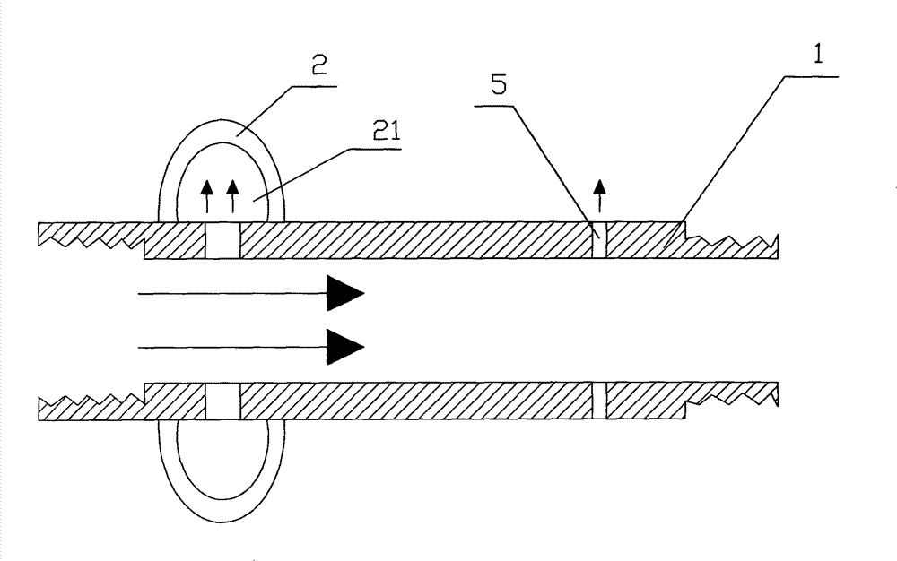
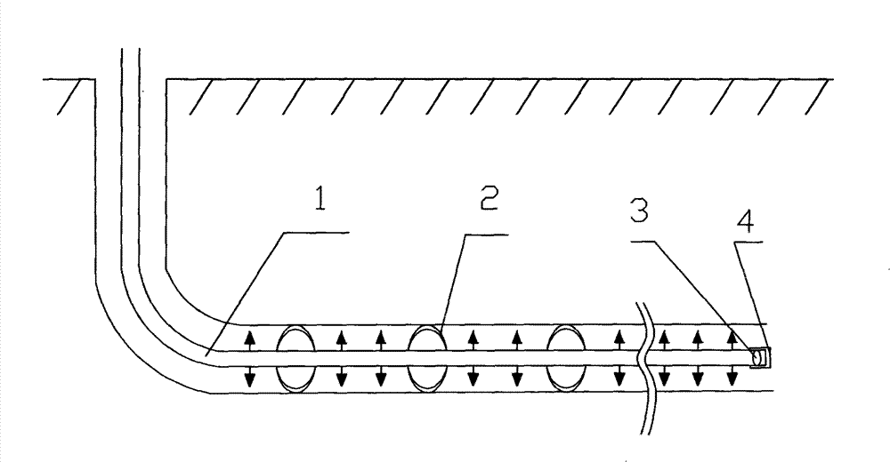
[0037] Such as image 3 As shown, the present invention is a controllable liquid injection pipe that is convenient for going into the well and lifting up, including the controllable liquid injection pipe 1. For the controllable liquid injection, the controllable liquid injection pipe of the present invention is provided with a throttle hole, so The diameter of the throttle hole is 0.2mm~5mm, because the diameter of the throttle hole is too small, image 3 The orifice is not drawn in, ( figure 2 The orifice 5) is marked in the middle, image 3 The direction of the middle black arrow is the injection direction through the orifice. In order to cut off the channeling of the injection medium in the annular space between the liquid injection pipe and the well wall and ensure the controllable liquid injection, the controllable liquid injection pipe of the present invention is provided with a bladder packer 2, such a...

Embodiment 2

[0039] Embodiment 2 Controllable Liquid Injection Pipe Structure

[0040] Such as image 3 As shown, the present invention is a controllable liquid injection pipe that is convenient for going into the well and lifting up, including the controllable liquid injection pipe 1. For the controllable liquid injection, the controllable liquid injection pipe of the present invention is provided with a throttle hole, so The diameter of the throttle hole is 0.2mm~5mm, because the diameter of the throttle hole is too small, image 3 The orifice is not drawn in, ( figure 2 The orifice 5) is marked in the middle, image 3 The direction of the middle black arrow is the injection direction through the orifice. In order to cut off the channeling of the injection medium in the annular space between the liquid injection pipe and the well wall and ensure the controllable liquid injection, the controllable liquid injection pipe of the present invention is provided with a bladder packer 2, such...

Embodiment 3

[0042] Embodiment 3 Controllable Liquid Injection Pipe Structure

[0043] Such as image 3 As shown, the present invention is a controllable liquid injection pipe that is convenient for going into the well and lifting up, including the controllable liquid injection pipe 1. For the controllable liquid injection, the controllable liquid injection pipe of the present invention is provided with a throttle hole, so The diameter of the throttle hole is 0.2mm~5mm, because the diameter of the throttle hole is too small, image 3 The orifice is not drawn in, ( figure 2 The orifice 5) is marked in the middle, image 3 The direction of the middle black arrow is the injection direction through the orifice. In order to cut off the channeling of the injection medium in the annular space between the liquid injection pipe and the well wall and ensure the controllable liquid injection, the controllable liquid injection pipe of the present invention is provided with a bladder packer 2, such...


PUM


Abstract

The invention discloses a controllable liquid injection pipe convenient for descent and lifting and a controllable liquid injection method. The controllable liquid injection pipe convenient for descent and lifting comprises a controllable liquid injection pipe, wherein the controllable liquid injection pipe is provided with a pressure opener which is not closed after being opened, and after the pressure opener is opened, the controllable liquid injection pipe is excellently communicated with the outside by the pressure opener, thus, when the controllable liquid injection pipe is lifted, because the inside and the outside of the controllable liquid injection pipe are excellently communicated, the inside and outside pressure difference of the controllable liquid injection pipe is greatly reduced, the contracted state of a bladder-type packer is guaranteed, and the bladder is prevented from being damaged and the skin of the bladder is prevented from outwardly rolling caused by the friction between the expanded bladder-type packer and the well wall so as to be convenient for lifting the liquid injection pipe out from an oil well, a gas well or an injection well, the lifting speed of the liquid injection pipe is greatly increased, and the normal production requirements of the oil field are satisfied. The controllable liquid injection pipe is convenient for descent and lifting, has flexible utilization, simple operation, little liquid injection wastage and low expenditure and can realize controllable liquid injection.

Description

technical field [0001] The invention relates to a downhole liquid injection device and a liquid injection method used in the field of oil or natural gas exploitation, in particular to a controllable liquid injection pipe and a controllable liquid injection method that are convenient for going down the well and lifting up. Background technique [0002] According to the actual production needs of oil wells, gas wells or injection wells, it is necessary to inject a required amount of liquid or gas (collectively referred to as injection medium) into different formations during the oil or natural gas production process, such as water injection in the process of water flooding; Water steam injection is required in the production process; nitrogen injection is required in the water-gas alternate production process; sometimes different chemical agents need to be injected to meet production needs, such as to eliminate clogging substances around the well wall of oil wells, gas wells or...

Claims


Application Information

Patent Timeline
Patent Type & Authority Patents(China)
IPC IPC(8): E21B21/16E21B43/20E21B43/22E21B43/27
Inventor 裴柏林吴建昌薛泳
Owner ANTON BAILIN OILFIELD TECH (BEIJING) CO LTD
Why Eureka
Try Eureka