
Convection tide-discharge heat conducting wood floor block and wood floor spliced thereby

A technology for solid wood floors and floor boards, which is applied in heating methods, household heating, heating systems, etc., can solve the problems of polluting the environment, inability to keep paint flat, and difficult to promote and popularize.

Active Publication Date: 2009-07-29
陈洪淳
View PDF3 Cites 4 Cited by
  • Summary
  • Abstract
  • Description
  • Claims
  • Application Information

AI Technical Summary

Problems solved by technology

It’s just that during the production of plain boards, a lot of man-made board consumption has been increased, and the processing output rate is 20%-30% higher than that of normal traditional flooring (traditional solid wood flooring is 3-5%), and a lot of time and labor are wasted during the production of the aforementioned special equipment. The cost makes the price of finished products much higher than that of traditional flooring, making it difficult to popularize
What's even more frightening is that the existing floor will form four exposed planes (wooden floor surface), and UV paint (it can be cured by ultraviolet rays) cannot be used, because ultraviolet curing is instant curing, because the existing wooden floor is The surface is four planes high and low, and the paint cannot be left flat in an instant, and the recesses cannot be polished. Now they are all sprayed with PU paint, which is a kind of natural drying.
It takes about 7 days for a batch of floor paint to be processed. The floor needs 3-4 coats of primer and 1-2 coats of top coat. Then it is 3-4 times of manual polishing of all parts of the floor concave. One person can only polish about 10 square meters , so that there is a great risk of occupational diseases for workers, and it also pollutes the environment

Method used


Image

  • Convection tide-discharge heat conducting wood floor block and wood floor spliced thereby
  • Convection tide-discharge heat conducting wood floor block and wood floor spliced thereby
  • Convection tide-discharge heat conducting wood floor block and wood floor spliced thereby

Examples


Embodiment Construction

[0036]In the following description, for simplicity, "floor board" and "floor" mean "solid wood floor board" and "solid wood floor". The longitudinal direction of the floor board is the direction consistent with the grain direction of the floor (usually the In the length direction, the expansion and contraction of the floorboard along this direction is very small), while the transverse direction of the floorboard refers to the direction perpendicular to the grain direction of the floor (usually the width direction of the floorboard, the expansion and contraction of the floorboard along this direction is the largest ), in addition, "solid wood floor board" should be understood in the broadest sense, for example, it can be understood as a floor board containing solid wood with tidal shrinkage properties, which can be composed of one or more layers of solid wood; "horizontal convection trough" It refers to the convection groove formed at the bottom of the "transverse groove" and th...


PUM


Abstract

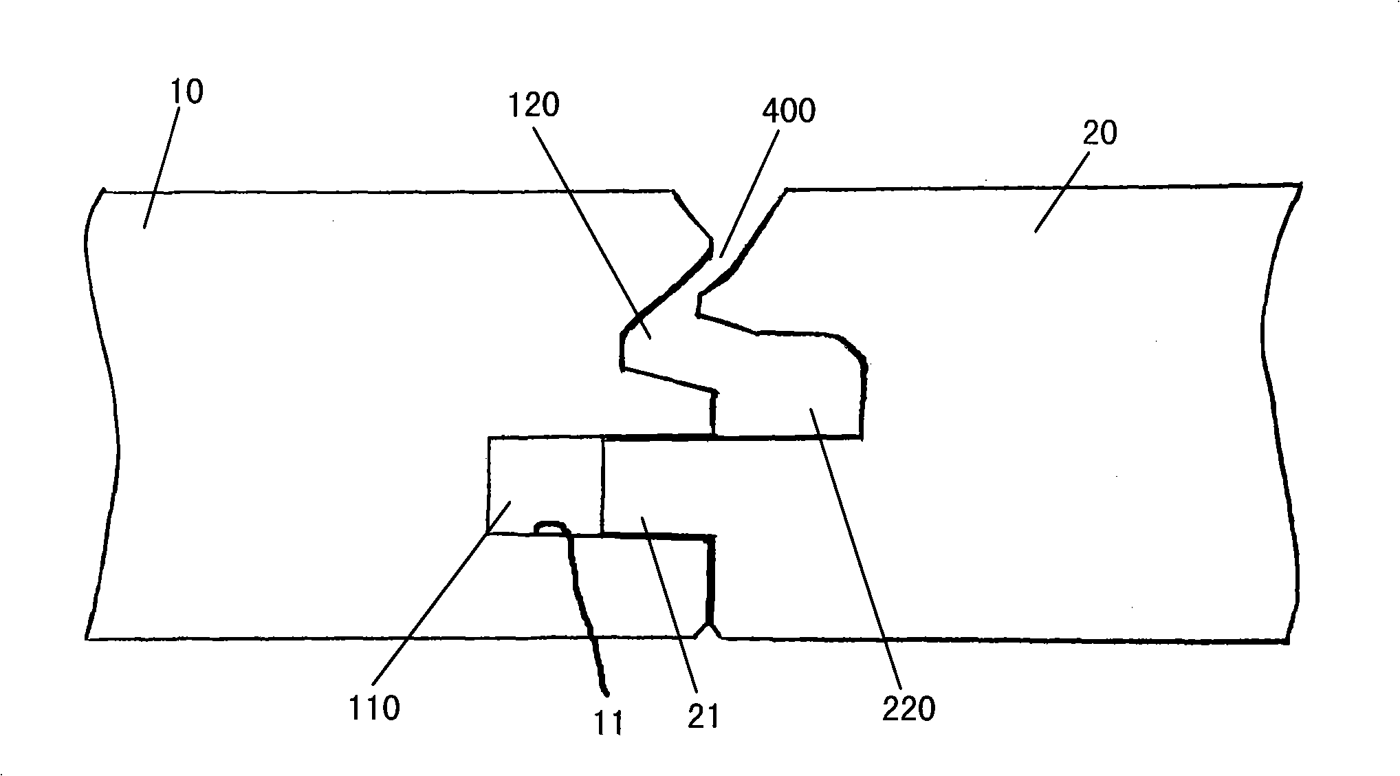
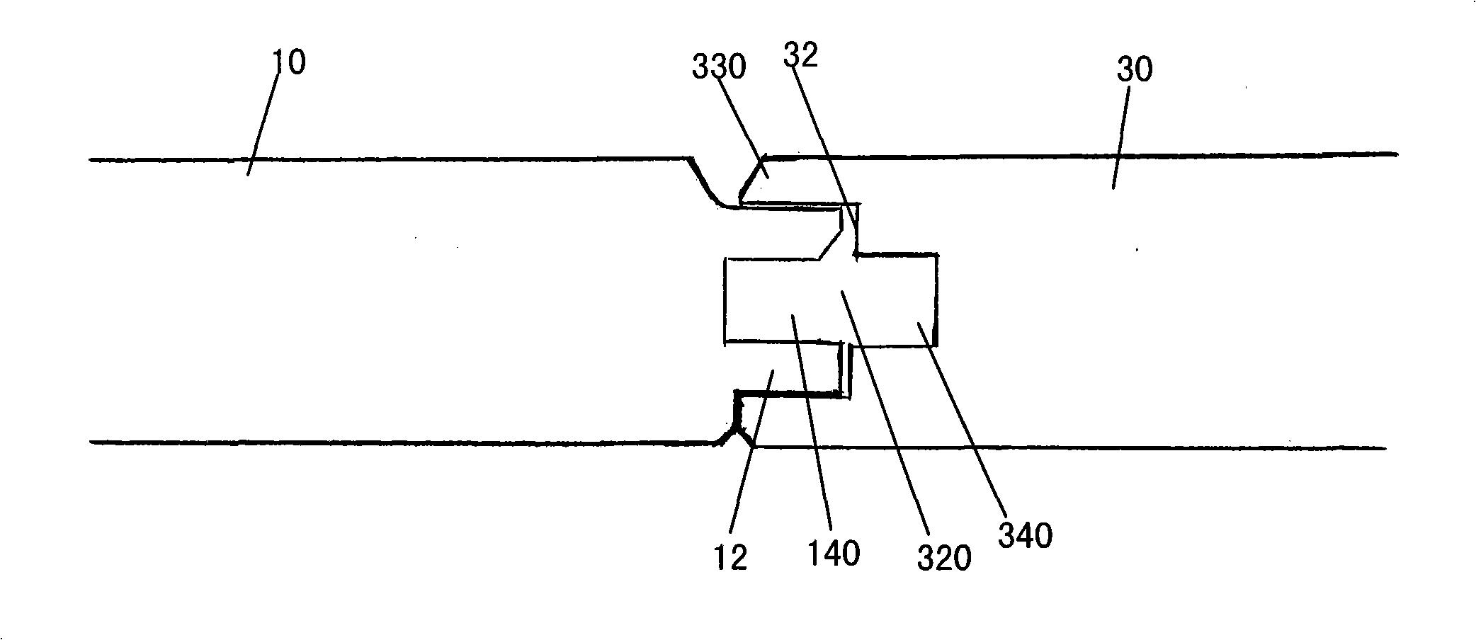
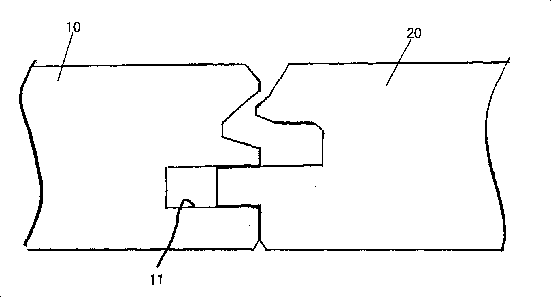
The invention discloses convection-type damp-discharging and heat-conducting solid wood floor blocks, which can be spliced to form the damp-discharging and heat-conducting solid wood floor and the back of which is formed with a longitudinally-through air guide groove, a longitudinal first end forms a transverse groove, a transverse first side forms a longitudinal tenon, a longitudinal second side forms a longitudinal groove, and the air guide groove is communicated with the transverse groove; the invention is characterized in that the bottom of the transverse groove forms a transverse convection groove, the depth of the longitudinal groove is larger than the length of the longitudinal tenon, the bottom of the longitudinal groove forms a longitudinal convection groove, the transverse convection groove and the longitudinal convection groove are at least partially intercrossed to be communicated with each other, two solid wood floor blocks form a transverse joint seam by abutting the longitudinal first end of one solid wood floor block against to the longitudinal second end of the other solid wood floor block, and the longitudinal convection groove is communicated with the transverse joint seam.

Description

technical field [0001] The invention relates to a solid wood floor, in particular to a ground heating solid wood floor. Background technique [0002] Solid wood flooring is an object that does not conduct electricity and has poor thermal conductivity. Solid wood flooring has a natural property of rising and shrinking due to changes in moisture content. Due to the aforementioned reasons, solid wood flooring is not suitable for ground heating technology, which makes solid wood flooring basically out of the area where heating is widely used. In addition, if you accidentally pour liquid on the solid wood floor, you must repair the solid wood floor, otherwise the solid wood floor will arch. [0003] People try to change the characteristics of solid wood's ebb and flow and shrinkage through chemical modification of solid wood, drying temperature and other aspects, but these studies are difficult to make progress. [0004] On the other hand, people also prevent arching or shrink...

Claims


Application Information

Patent Timeline
Patent Type & Authority Applications(China)
IPC IPC(8): E04F15/04
CPCE04F15/04F24D3/12F24D5/06E04F2201/0107E04F2290/023E04F2201/025F24D3/127Y02B30/00
Inventor 陈洪淳
Owner 陈洪淳
Learn More